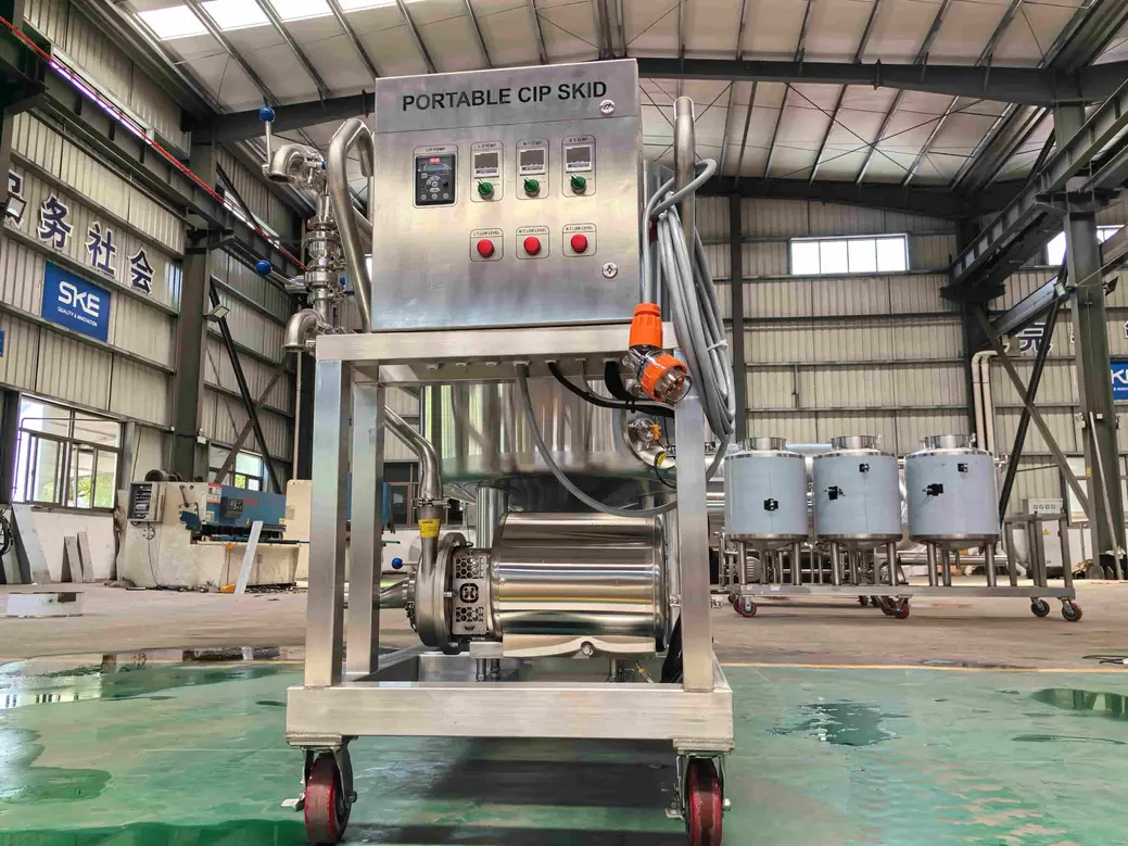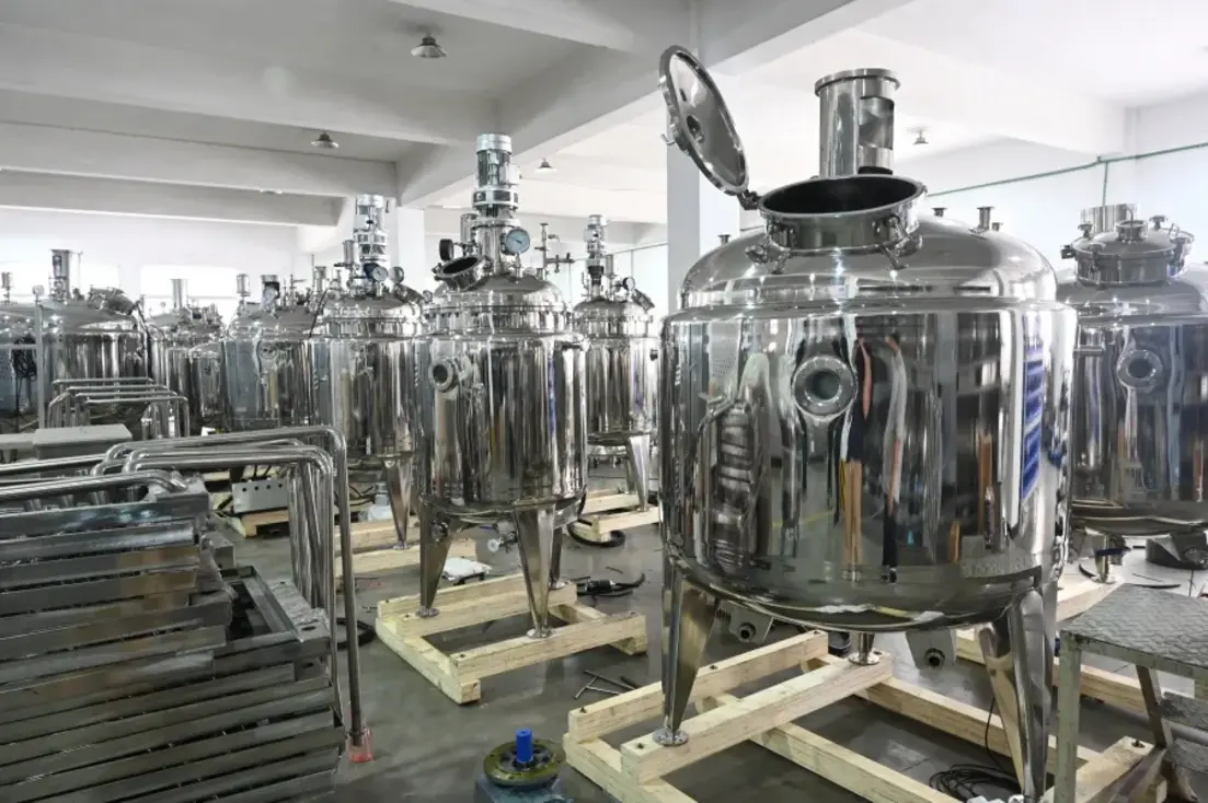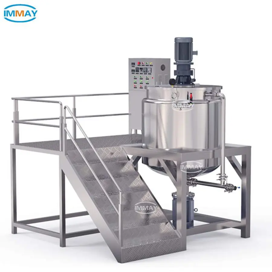
CIP cleaning mixing tanks is reliable only when the complete cleaning circuit works as one system: the vessel geometry, agitator and internals, spray device, supply flow, cleaning recipe, return path, and drainage all have to be suitable. A well-sized CIP skid cannot correct a tank with inaccessible surfaces, persistent spray shadows, poor drainage, or a blocked return path.
The practical starting point is to map every product-contact surface and ask two questions: how does cleaning solution reach it, and how does solution and soil leave it? That assessment determines whether a static spray ball is adequate, whether a rotary device is needed, where devices should be mounted, and what evidence is required to demonstrate repeatable cleaning.
Start with the tank, not the spray device
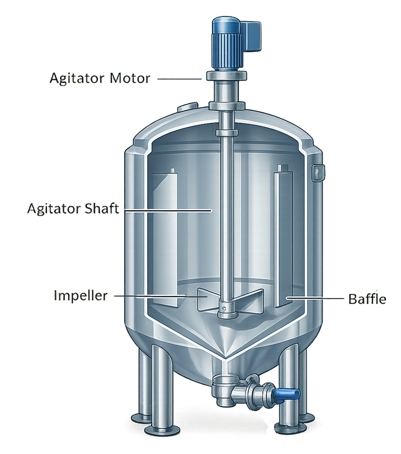
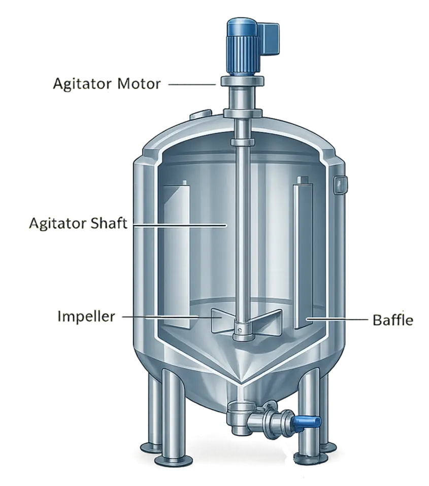
Mixing tanks are more difficult to clean than plain storage vessels because their internals interrupt the liquid pattern. Product can remain on the underside of an impeller, behind baffles, at shaft seals, around probes, below manways, in dip pipes, and at the tank bottom or outlet.
Before selecting or changing a mixing tank CIP spray ball, document the actual as-built vessel rather than relying only on a general arrangement drawing. Include:
- Tank diameter, straight-side height, head shape, and bottom geometry
- Top entries, manways, sight glasses, lights, vents, sampling connections, and instruments
- Agitator shaft, impeller type and elevation, support structure, and any shaft seal flush arrangement
- Baffles, coils, recirculation pipes, dip tubes, level probes, and other internal fittings
- Product outlet position, valve arrangement, and low points
- CIP supply connection, device mounting point, return route, and venting provisions
- Product characteristics, including whether it dries, burns on, forms films, contains fat or protein, or includes sticky particulates
Source: usvalidation
This review often identifies a design limitation before the cleaning recipe is considered. For example, a centrally mounted spray device may wet much of the shell but leave a shadow behind a baffle or beneath a large agitator hub. A device may also clean the vessel effectively while a connected branch, seal circuit, or outlet valve remains outside the intended cleaning path.
Understand the four cleaning inputs
CIP performance depends on the combined effect of time, mechanical action, chemical action, and temperature. These factors are often described as TACT. Changing one factor may require adjustment of another, but substitutions are not automatic. More chemical strength does not necessarily overcome inadequate surface wetting, and a longer cycle does not necessarily clean a sheltered deposit.
For a mixing tank, mechanical action may come from several sources:
- Flow and impingement from the spray device
- A flowing film over vessel walls and heads
- Recirculation through connected process piping
- Agitator operation, where the equipment manufacturer and site procedure allow it during CIP
Cleaning chemicals, concentration, temperature, sequence, and contact time should be established for the actual soil, materials of construction, seals, and food-safety program. Use chemical supplier instructions, equipment documentation, and the plant’s validated sanitation procedures. Do not transfer settings from another product or tank solely because the vessels appear similar.
Select a spray device by cleaning duty
The right device is not simply the one that advertises the widest nominal spray pattern. Selection should be based on hydraulic performance at the installed flow and pressure, the tank layout, the soil level, and the required cleaning evidence.
| Device type | Typical cleaning approach | Best fit | Main limitation to check |
|---|---|---|---|
| Static spray ball | Distributed jets or spray create a wetted film over surfaces | Simple vessels with readily removable soils and limited internals | May provide insufficient force in shadowed or heavily soiled areas |
| Static spray nozzle | Fixed directional jets target selected areas | Supplementing a known difficult area or a specific fitting | Requires careful orientation and may not address changing obstructions |
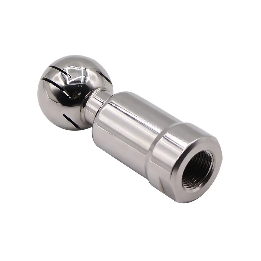
| Rotary spray device | Moving jets sweep the vessel in a repeatable pattern | Tanks with complex internals, difficult soils, or areas needing more mechanical action | Must receive the specified hydraulic conditions and remain serviceable |
| Multiple devices | Separate devices address distinct vessel zones | Tall, large-diameter, divided, or heavily obstructed vessels | Device interaction, supply capacity, and complete drainage need review |
A static spray ball can be effective where liquid distribution and film coverage are sufficient for the tank and soil. It is not inherently unsuitable. However, it should not be assumed to clean behind every obstruction merely because the device has broad nominal coverage.
A rotary spray device tank cleaning arrangement can provide more focused, moving mechanical action. It may be appropriate where baffles, impellers, viscous residues, or large dimensions make simple film coverage uncertain. Rotary devices also introduce practical requirements: correct orientation, filtration appropriate to the device, adequate supply conditions, inspection and maintenance of moving parts, and confirmation that the device operates as intended during the cycle.
Check the manufacturer’s hydraulic data at installed conditions
Spray-device literature commonly provides a recommended flow range and pressure or pressure-loss information. Compare that information with the pressure and flow available at the device, not only at the CIP skid discharge.
Pressure can be lost through long supply lines, undersized piping, valves, strainers, elevation changes, and other equipment operating in parallel. If several tanks or devices clean at once, the available flow can also differ from single-device conditions. Record the intended valve lineup and operating configuration as part of the recipe.
Design for coverage and return flow together
Coverage is only half the cleaning problem. The cleaning solution must also drain or return without pooling, dilution problems, or re-deposition of released soil.
Review the following areas during design or troubleshooting:
Vessel walls, heads, and top fittings
Confirm that the spray pattern reaches the upper head, manway underside, vent connections, and every top-mounted fitting. A top-mounted device can be obstructed by a central shaft, access cover, sensor, or mounting hardware. The underside of a raised manway cover is a common area to examine directly.
Agitator and shaft seal area
Define whether the agitator is stationary or running during each CIP step. If it operates during cleaning, the procedure must be compatible with the mixer design, mechanical seal arrangement, liquid level, and safety controls. If it remains stationary, inspect the surfaces behind blades, hubs, and supports for shadowing.
The shaft seal and any associated flush or barrier system require their own cleaning and maintenance plan. Do not assume spray inside the tank automatically cleans all seal-related product-contact passages.
Baffles and internal pipes
Baffles create narrow zones between the baffle and vessel wall. Internal pipes, coils, and dip tubes can block a spray path and create sheltered undersides. Direct observation during water trials is especially useful for these features.
Bottom, outlet, and return path
The vessel should drain toward a usable low point, and the outlet, valve body, and return piping must be included in the intended circuit. Poor drainability can leave diluted chemical, rinse water, or soil-containing liquid behind after the cycle. It also makes repeatable cleaning harder to demonstrate.
Hygienic design guidance commonly emphasizes avoiding pockets, crevices, and unnecessary dead legs, along with providing drainable pipework. Where a branch cannot be avoided, assess whether it is actually swept by the cleaning circuit and whether it can be inspected or otherwise verified.
Perform CIP coverage testing before validation
CIP coverage testing asks a physical question: does the cleaning liquid reach the surfaces it is expected to clean? It is an important commissioning and troubleshooting activity, but it is not by itself proof that product residues or microorganisms have been removed to the plant’s acceptance criteria.
A practical coverage-test approach is:
- Set the intended CIP configuration. Use the same supply path, valve lineup, device arrangement, and approximate operating conditions that the cleaning recipe will use.
- Prepare the vessel safely. Apply the site’s lockout, confined-space, chemical-handling, and access procedures. Do not enter a tank or defeat safeguards merely to observe spray behavior.
- Use a suitable visible indicator. Many plants use a water-sensitive or other compatible coverage medium placed at representative locations. The indicator must not introduce contamination or damage product-contact surfaces.
- Place indicators at credible worst-case points. Include areas behind baffles, under impellers, around shafts, beneath fittings, at the upper head, in the lower shell, and near outlet geometry.
- Run the relevant spray step. Record supply flow, pressure where measured, device operating state, duration, and any simultaneous demand on the CIP system.
- Inspect and document results. Identify incomplete wetting, delayed wetting, abnormal device motion, pooling, or areas affected by obstructions.
- Correct the cause and repeat. Possible changes include device position, device type, added targeted nozzles, revised piping, altered sequencing, or hygienic redesign of an internal feature.
Source: m.media-amazon
Coverage tests should be repeated after meaningful changes. Examples include a new impeller, added sensor, altered baffle, replacement spray device, changed CIP pump, piping modification, or revised recipe. A coverage result from the original tank configuration is not automatically valid after an internal change.
Build food tank cleaning validation around risk and evidence
Food tank cleaning validation establishes documented evidence that a defined cleaning process achieves predetermined acceptance criteria for its intended use. The exact methods should reflect the product hazards, changeover risks, soil type, equipment design, and applicable customer or regulatory requirements.
A validation plan commonly includes the following elements:
- A clear description of the tank, internals, connected piping, spray devices, and cleaning circuit
- Defined cleaning steps, including rinses, chemical washes, intermediate rinses, and sanitation where applicable
- Specified operating ranges for relevant variables such as flow, temperature, chemistry, and time
- Identification of worst-case products, soils, changeovers, and hard-to-clean locations
- A sampling plan with justified locations and methods
- Predefined acceptance criteria for visible residue, chemical carryover, allergens where relevant, microbiological indicators, or other site-defined risks
- Repeatability evidence across representative cleaning runs
- Deviation handling, corrective actions, and change-control requirements
The sampling method must fit the surface and hazard being evaluated. Visual inspection can detect obvious residues and gross failures, but it cannot demonstrate cleanliness in inaccessible areas. Swab sampling may be useful at accessible high-risk locations. Rinse sampling can provide information about the circuit, but it may not identify the exact source of a failure. Plants often use more than one line of evidence.
Do not treat a passing ATP, protein, allergen, conductivity, pH, or microbiological result as interchangeable with every other result. Each test answers a different question and has limitations. The sanitation team should define what each test is intended to demonstrate, how samples are collected, and what action follows an out-of-specification result.
Establish operating controls after validation
Once the tank and cycle have been validated, daily reliability depends on controlling the validated conditions. A useful operating record can include:
- Recipe name and tank identification
- Product or campaign cleaned
- CIP start and completion status
- Confirmed valve lineup or automated route status
- Supply and return conditions specified by the procedure
- Chemical concentration verification method and result
- Relevant time and temperature records
- Flow or pressure confirmation where these are critical to spray-device performance
- Conductivity, rinse endpoint, or other approved process checks
- Deviations, alarms, corrective actions, and release authorization
Trend these records rather than reviewing them only after a failure. Repeated low flow, a gradually longer rinse endpoint, recurring conductivity deviations, or frequent spray-device maintenance can indicate a developing problem before a cleaning verification failure occurs.
Common CIP failures in mixing tanks
The tank walls look clean, but residue is found near the agitator. Inspect impeller undersides, shaft supports, baffle gaps, and the seal area. The likely issue is localized shadowing or inadequate mechanical action, not necessarily a general lack of chemical strength.
A rotary device does not perform consistently. Verify actual supply conditions, upstream restrictions, filters, device orientation, and maintenance condition. Confirm that the device receives the conditions specified by its manufacturer throughout the cycle.
The cycle passes when the tank is empty but fails after production. Review the product soil, hold time before cleaning, product temperature during processing, and whether residues dry or harden. The tested soil must represent normal and worst-case operating conditions.
Cleaning results vary by shift. Compare manual steps, pre-rinse timing, valve lineups, chemical preparation, and whether the same CIP recipe is consistently selected. Automation improves repeatability only when instruments, valve feedback, and procedures are maintained.
Rinse results remain inconsistent. Investigate drainage, pooled liquid, shared return routes, valve leakage, trapped branches, and the possibility of cleaning solution entering or remaining in an unintended circuit.
Practical decision checklist
Before approving a new or revised tank-cleaning arrangement, confirm that the team can answer these questions:
- Are all product-contact surfaces, including internals and connected branches, identified?
- Does each surface have a credible wetting and soil-removal mechanism?
- Is the selected spray device supplied within its documented operating range at the point of use?
- Have shadow zones around agitators, baffles, probes, and manways been tested?
- Can cleaning solution and released soil return and drain without pooling?
- Are the cleaning chemistry and cycle conditions appropriate for the actual product soil and equipment materials?
- Has the cleaning process been validated with predefined, risk-based acceptance criteria?
- Are critical operating conditions monitored and controlled in routine production?
- Does the change-control process require reassessment after tank or CIP modifications?
Reliable CIP cleaning mixing tanks is an engineering and sanitation discipline, not a spray-device purchase decision. A properly selected device matters, but dependable results come from treating the tank, internals, hydraulics, chemistry, drainage, and verification methods as one controlled cleaning system.
References
- CIP Cleaning (Clean-in-Place): Meaning, Process & Tank Requirements. (n.d.). https://www.behaelter-kg.de/en/insights/cip-cleaning-significance-procedure-and-technical-requirements.html
- What is CIP Cleaning or Clean-In-Place Cleaning?. (n.d.). https://sanimatic.com/what-is-cip-cleaning
- Pharmaceutical Tank Cleaning and CIP Integration. (n.d.). https://usvalidation.com/kb_article/tank-cleaning-integration
- Material & Surface Finish Standards for Hygienic Mixing Tanks. (n.d.). https://www.fulukemix.com/article/material-surface-finish-hygienic-mixing-tanks
- Sanitation Performance Standards Compliance Guide | Food Safety and Inspection Service. (n.d.). http://www.fsis.usda.gov/inspection/compliance-guidance/sanitation-performance-standards-compliance-guide
- CIP Rotary Spray Ball Guide: 360° Tank Cleaning. (n.d.). https://spikmachinery.com/cip-rotary-spray-ball-guide-how-360-zero-blind-spot-cleaning-works
- CIP/COP Archives - M.G. Newell. (n.d.). https://www.mgnewell.com/tag/cip-cop
- CIP Spray Nozzles | Clean-In-Place Systems for Food & Bev. – NozzlePro. (n.d.). https://nozzle-pro.com/pages/tank-vessel-cleaning-cip-clean-in-place