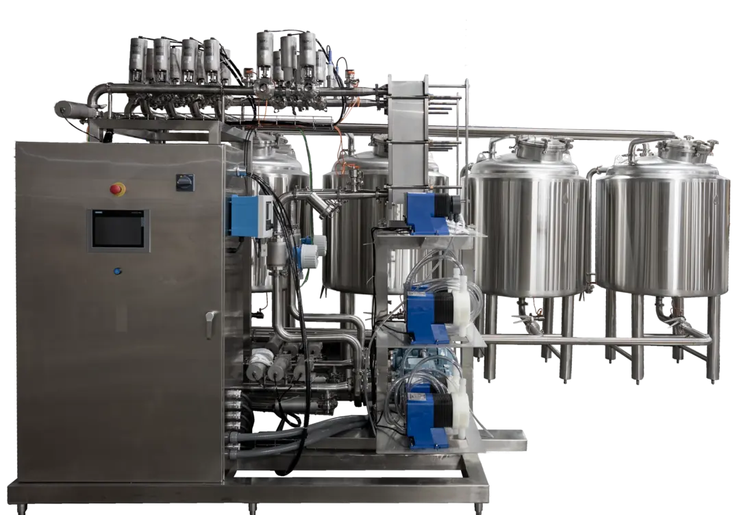
A CIP system design for food plants is not simply a set of chemical tanks and a pump. It is a controlled cleaning system that must deliver the right cleaning media, at a suitable flow, temperature, concentration, and duration, to every intended product-contact surface—and then bring that media back through a return path that confirms the circuit was actually reached.
When one line cleans reliably while another retains residue, consumes too much water, or produces inconsistent results, the cause is often in circuit design rather than the nominal cleaning recipe. A dead leg, an incorrectly routed valve, inadequate return flow, a weak tank spray pattern, or an oversized shared circuit can prevent a well-intended cycle from producing repeatable cleaning.
What a CIP system does
Clean-in-place (CIP) is a method for cleaning internal product-contact surfaces without routine dismantling. It is commonly used for piping, tanks, valves, pumps, heat exchangers, fillers, and other enclosed sanitary process equipment.
A typical cycle may include one or more rinses, chemical cleaning steps, intermediate rinsing, and a final step defined by the plant’s sanitation program. The exact sequence and conditions depend on the product, soil, equipment geometry, materials of construction, water quality, chemical supplier guidance, and the facility’s validated procedures.
CIP does not make poorly designed equipment cleanable by itself. Product-contact surfaces still need hygienic construction, accessible drainage, appropriate slopes, suitable seals, and connections that do not trap product or cleaning solution. Equipment that requires inspection or manual cleaning should remain in the sanitation plan even if it is connected to a CIP system.
The basic CIP circuit
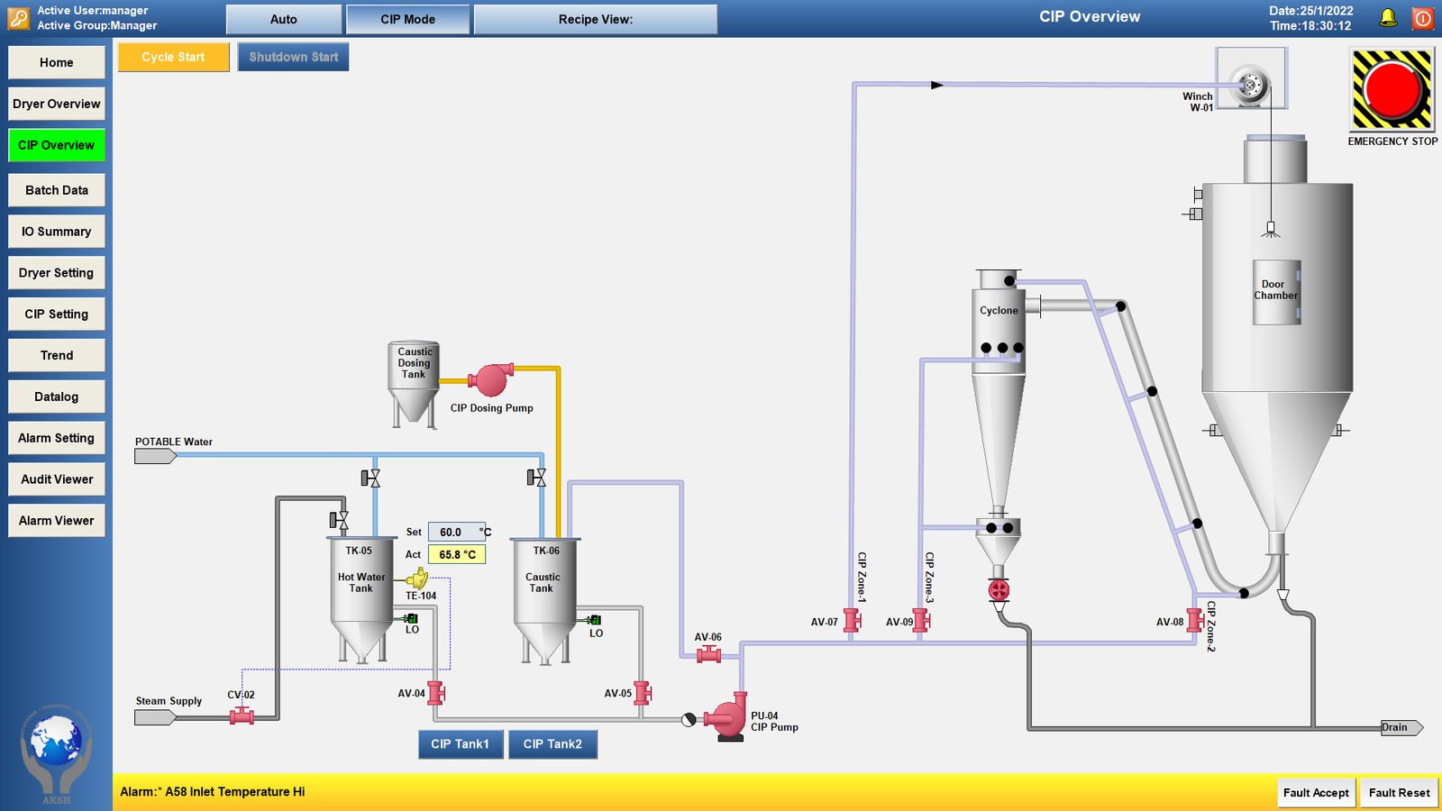
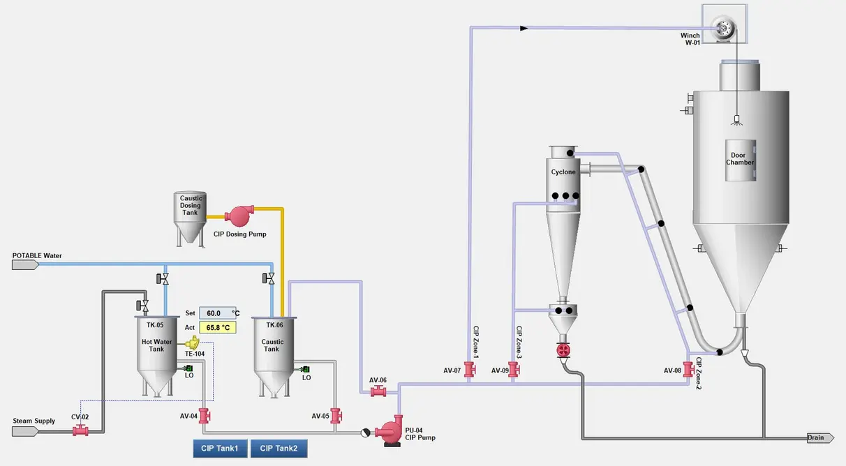
A CIP circuit is the defined route taken by cleaning media through a group of process components. It begins at the CIP skid or supply source, passes through selected equipment, and returns to a designated recovery, drain, or return tank.
The key design question is simple: can the system prove that cleaning solution traveled through the complete intended route with adequate conditions?
A practical circuit includes:
- CIP tanks, holding water, recovered solution, or prepared cleaning solution.
- Supply pumps, providing the pressure and flow needed for piping and spray devices.
- Heating equipment, where required to maintain the intended cleaning temperature.
- Chemical dosing and concentration controls, often supported by conductivity measurement or other plant-approved methods.
- Supply piping and automated valves, directing media to the selected route.
- Process equipment, such as tanks, pipelines, pumps, valves, or heat exchangers.
- Return piping, carrying the cleaning media back while providing useful evidence that the route was completed.
- Instrumentation and controls, including flow, temperature, conductivity, level, valve-position, and timing signals as appropriate.
Source: akshengineering
Circuit segregation: why one CIP route should not try to clean everything
CIP circuit design starts with separating equipment into groups that can be cleaned under compatible conditions. A small-diameter pipeline, a large process tank, and a heat exchanger may all require cleaning, but they do not necessarily need the same hydraulic conditions or the same sequence.
Overly broad circuits can create several problems:
- A pump may provide adequate flow in one branch but not another.
- A tank-cleaning device may receive insufficient pressure when other paths are open.
- Long lines can add excessive volume, increasing rinse-water use and delaying chemical recovery.
- Parallel paths can divide flow unpredictably.
- A cleaning solution can bypass a difficult branch through a lower-resistance route.
- Different soils may require different cleaning approaches or different verification methods.
Segregation does not always mean installing a separate CIP skid for every line. It means defining manageable circuits, controlling their valve paths, and confirming that each circuit receives the necessary cleaning conditions. A plant may use one central skid to service multiple circuits sequentially, provided the controls and piping arrangement prevent unintended cross-connections.
CIP supply and return line design
The supply line gets most of the attention because it carries pumped cleaning media to the process area. The return line is equally important. A circuit cannot be assumed clean merely because the supply pump ran for a programmed period.
Supply-side priorities
Supply piping should be sized and routed to deliver the required flow to the farthest and most demanding part of the circuit. Restrictions, unnecessary elevation changes, poorly selected valves, and excessive branch complexity can reduce the flow available at the equipment.
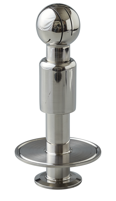
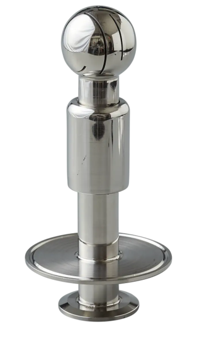
For tank circuits, the design must account for the cleaning device. Static spray balls and dynamic spray devices operate differently, and their performance depends on the flow and pressure delivered at the device—not just the pump’s rated condition at the skid.
Return-side priorities
Return lines must remove spent solution, dislodged soil, and rinse water without creating unwanted hold-up or backpressure. They should support drainage and avoid conditions where liquid pools after the cycle.
Return conditions also provide operational information. A return temperature can indicate whether hot cleaning media reached the circuit. Conductivity can help distinguish water from recovered chemical solution or show a transition between steps. Flow, pressure, level, or return timing may also be useful signals, depending on the circuit.
A return signal is not a universal proof of cleanliness. It is evidence that media returned from a route under defined conditions. Its meaning must be established as part of the plant’s validation and monitoring approach.
Flow velocity and mechanical action
Cleaning depends on more than chemistry. In straight pipe circuits, liquid flow creates wall shear that helps remove residue and carry it away. The needed hydraulic conditions vary with pipe size, product characteristics, soil condition, length, fittings, and equipment design.
For this reason, CIP flow velocity in food processing should be treated as a circuit-specific engineering requirement, not a single plant-wide number. A velocity calculated at the CIP skid may not represent the velocity in every branch, especially where circuits divide or contain restrictions.
Design reviews should ask:
- What is the expected flow in each branch and at the farthest point?
- Are there parallel paths that could split or short-circuit flow?
- Are pumps, valves, heat exchangers, and instruments compatible with the required CIP flow?
- Can the circuit drain after cleaning?
- Are difficult geometries, low points, flexible hoses, sample points, or bypasses included in the route?
Temperature, chemical concentration, and time as controlled conditions
Temperature, chemical concentration, and contact time work together with mechanical action. The correct combination cannot be chosen from a generic recipe because it depends on the specific soil and process equipment.
Temperature must be measured where it matters. A temperature at the CIP skid may differ from the temperature reaching a distant tank, long branch, or heat exchanger. Heat losses, cold equipment mass, and slow circulation can affect actual conditions at the cleaning surface.
Conductivity monitoring is commonly used as an operational indicator of solution concentration or interface changes between water and cleaning solution. But conductivity is influenced by the chemical system, water quality, temperature, and instrument setup. It should be correlated with the plant’s approved chemical-control method rather than treated as a stand-alone measurement of cleaning effectiveness.
Time should likewise be tied to the actual circuit state. A programmed step duration is meaningful only if the circuit had reached the intended flow, temperature, and concentration conditions. Controls may therefore distinguish between filling, heating, circulation, recovery, and rinse phases rather than treating the entire sequence as one undifferentiated timer.
Tank spray devices and difficult equipment
Tanks need complete internal wetting and sufficient mechanical action from their selected spray device. Device selection should consider tank diameter and height, internal obstructions, agitators, shadow areas, vessel geometry, product behavior, and the available pump duty.
Source: glaciertanks
A spray device is not a substitute for hygienic vessel design. Internal components, gasketed connections, instruments, vent paths, and agitator assemblies can create difficult areas. These features should be reviewed with the equipment manufacturer and included in the cleaning and verification plan.
Heat exchangers, fillers, valve clusters, and complex manifolds also require special attention. Their internal paths may not be obvious from an external piping drawing. A circuit review should trace the actual cleaning route through every valve position and component, not merely assume that a product route is automatically a cleanable route.
What CIP controls can verify—and what they cannot
Automated records make CIP more repeatable and traceable. A control system can record selected conditions such as recipe selection, valve states, pump operation, flow, temperature, conductivity, levels, alarms, and cycle completion.
These records can show whether a cycle ran within its defined operating envelope. They cannot, by themselves, establish that every soil type, allergen concern, or microbiological hazard was adequately controlled. Cleaning effectiveness must be validated and periodically verified using methods appropriate to the product, equipment, hazard analysis, and facility requirements. Those methods may include inspection, residue checks, targeted sampling, or other procedures set by the plant’s food-safety program and applicable authorities.
Do not respond to a failed verification result only by increasing chemical strength, temperature, or cycle time. First investigate the circuit: valve routing, flow distribution, return behavior, spray-device condition, drainage, equipment damage, product buildup, and changes in the product or production schedule may be contributing factors.
CIP design-review checklist
Before approving a new or modified system, review the following points:
- Define every CIP circuit and its intended equipment boundaries.
- Trace supply and return routes for every automated valve configuration.
- Confirm that circuits are segregated where hydraulic or soil conditions differ materially.
- Verify that the pump can meet the required duty at the actual circuit, not only at the skid.
- Check flow distribution through parallel branches and bypass paths.
- Review tank spray-device coverage, pressure, flow, and internal obstructions.
- Ensure supply and return piping supports drainage and minimizes liquid hold-up.
- Identify dead ends, low points, sample valves, hoses, instruments, and other hard-to-clean features.
- Measure critical conditions at meaningful points, including remote locations where needed.
- Define how conductivity, temperature, flow, and return signals will be interpreted.
- Build alarms and interlocks around credible failure modes, such as incorrect valve position, low flow, low return, or insufficient temperature.
- Establish validation and verification methods with qualified sanitation, quality, engineering, and chemical-supplier input.
- Maintain records of circuit changes, valve logic changes, new products, and equipment modifications.
A well-designed CIP system is a coordinated cleaning route, not just a programmed sequence. When circuits are clearly defined, supply and return paths are engineered together, and operating signals are connected to meaningful verification, the plant is in a stronger position to clean consistently while avoiding unnecessary water, chemical, and downtime costs.
References
- CIP System Design for Food Processing Tanks - VINMAY. (n.d.). https://vinssco.com/cip-system-design-for-food-processing-tanks
- CIP Systems Guide: Design and Operation. (n.d.). https://www.ske-eagle.com/comprehensive-guide-to-cip-systems-design-operation-and-applications
- Cleaning in Place Equipment | Smart CIP System for Food Plants. (n.d.). https://www.easireal.com/cip-machine-product
- CIP Cleaning Guidelines: Best Practices for UF, NF, and RO. (n.d.). https://h2operators.com/cip-cleaning-best-practices
- Clean in Place, CIP Solutions for Sanitary Process Systems for Dairy, Wineries, Breweries, Food and Beverage. (n.d.). https://www.placerprocesssystems.com/sanitary-process-systems-products/clean-in-place-cip
- Clean in Place (CIP) Complete Guide: What It Is, How It Works, Procedure, Design & Maintenance - Nanjing Hjchem Equipment Co.,Ltd. (n.d.). https://njhjchem.com/clean-in-place-cip-complete-guide
- Sanitary Design and Construction of Food Equipment1. (n.d.). https://ucfoodsafety.ucdavis.edu/sites/g/files/dgvnsk7366/files/inline-files/26502.pdf
- Clean-In-Place (CIP) System | Korutek Engineering. (n.d.). https://korutek.com/clean-in-place-cip-system