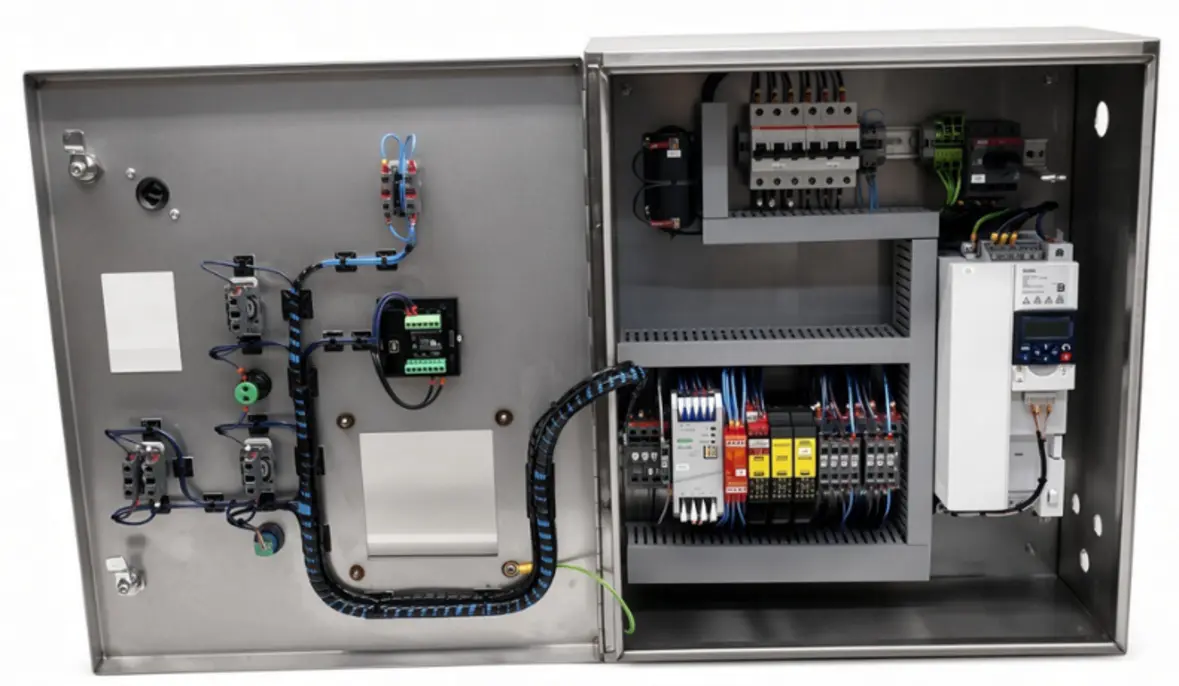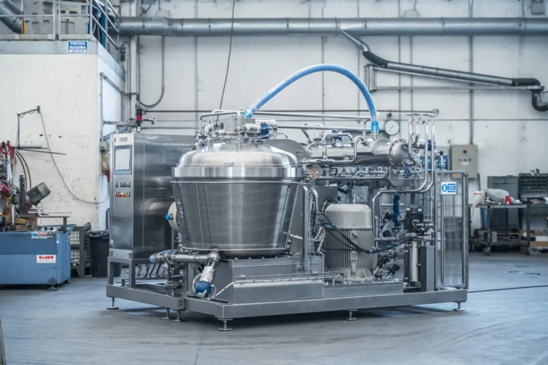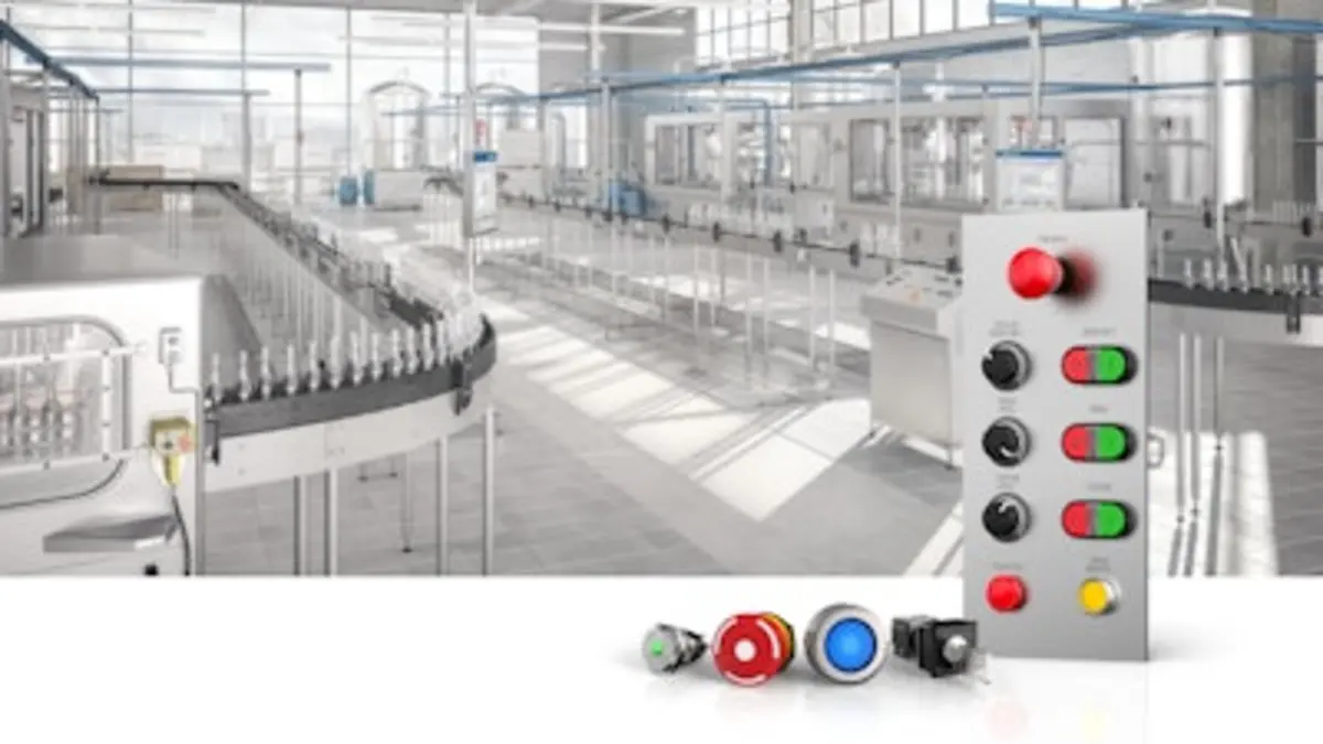
Food equipment OEMs get better machine quality and more predictable startup results when they separate responsibility for controls design from responsibility for panel assembly, field execution, and commissioning. Technicians remain essential, but their time is most valuable when they are building to released information, testing real hardware, resolving controlled exceptions, and feeding lessons back into the next design revision—not creating the initial electrical design and PLC logic while under installation pressure.
A practical food equipment OEM controls engineering workflow uses stage gates. Each gate confirms that the project has enough definition to move forward, identifies who owns the next decision, and prevents unreviewed field changes from becoming the de facto machine standard. The model is suitable for a single machine, a skidded process unit, or an integrated processing and packaging line.
The operating model: define, release, build, prove, install, improve
The core sequence is straightforward:
- Establish machine requirements and controls standards.
- Create and review the electrical and software design.
- Release controlled build packages to the panel shop and machine assembly team.
- Develop, simulate where practical, and test PLC and HMI software.
- Complete a factory acceptance test (FAT) against an agreed protocol.
- Commission the machine at the customer site within a controlled scope.
- Capture field lessons and turn approved changes into reusable standards.
This does not mean controls engineers should never visit a site or technicians should never suggest a design improvement. It means the normal path is clear: engineering owns the technical baseline; production owns workmanship to that baseline; commissioning owns execution and evidence; management owns staffing, priorities, and controlled change decisions.
Stage 1: Establish standards and project requirements
Before drafting a schematic or selecting a PLC, the OEM needs a defined machine requirement. This is the point where sales commitments, customer specifications, applicable project requirements, mechanical design decisions, utilities, environmental conditions, and integration interfaces become usable engineering inputs.
A controls standards owner—often a lead controls engineer, engineering manager, or designated technical authority—should maintain a controlled master standard covering such matters as:
- Preferred PLC, HMI, drives, safety components, network hardware, and power-control families
- Electrical drawing conventions, device tags, wire numbering, terminal practices, and revision control
- Panel layout rules, heat-management assumptions, enclosure selection criteria, and spare-capacity policy
- PLC program architecture, naming conventions, alarm philosophy, state logic, recipe handling, and diagnostic expectations
- HMI screen conventions, permissions, trends, alarm presentation, manual-control rules, and maintenance pages
- Network naming, IP-address allocation, remote-support policy, and customer plant interface requirements
- Documentation deliverables, backup expectations, and procedures for recording as-built changes
The standard should not be treated as a static PDF that technicians must interpret in the field. It should produce usable templates: schematic title blocks, bill-of-material structures, panel-layout blocks, PLC code libraries, HMI faceplates, alarm templates, and FAT checklists.
For food machinery, controls requirements also need to reflect the actual application. A washdown environment, a dry packaging room, a thermal process skid, and a raw-product handling conveyor may require different components, enclosure approaches, instrumentation, cleaning interfaces, and operating sequences. The OEM should verify customer requirements and applicable standards during engineering rather than attempting to retrofit them during startup.
Stage 2: Assign clear design ownership
The central management decision is to distinguish accountable ownership from supporting work.
| Work area | Primary owner | Key output | Typical support |
|---|---|---|---|
| Controls requirements and architecture | Controls engineering | Controls design basis and I/O concept | Project manager, mechanical engineering, customer contact |
| Electrical schematics and panel layout | Controls engineering | Released drawings and bill of materials | Panel shop, purchasing |
| PLC and HMI functional design | Controls engineering | Functional description, software structure, test plan | Process or mechanical engineering, technicians |
| Panel fabrication and internal wiring | Panel shop or electrical production | Built panel, inspection record, wiring corrections | Controls engineering |
| Machine wiring and device installation | Machine assembly or electrical technicians | Installed field devices and point-to-point checks | Controls engineering |
| FAT execution | Project team with defined test owner | Signed test record and issue list | Customer, quality, service |
| Site commissioning | Commissioning lead | Startup record, site changes, acceptance evidence | Controls engineering, customer operations |
| Standard updates and training | Engineering leadership | Revised masters and training material | Technicians, service, quality |
A technician can contribute substantially to design reviews, panel-layout practicality, maintainability, and startup diagnostics. The problem begins when the same person is expected to choose components, create the schematic, write unstructured PLC code, wire the panel, debug the machine, travel to site, and document changes without protected engineering time or independent review. That arrangement concentrates risk in one role and makes consistency difficult to maintain.
Stage 3: Use reusable master designs without forcing a bad fit
Reusable master designs reduce repeat errors and speed delivery, but only if they are governed. A master machine controls package should include a proven architecture and defined options—not a collection of old projects copied forward.
A useful master package may contain:
- Base electrical schematic sections and approved option modules
- Standard control-panel layouts for common machine sizes or I/O ranges
- Reusable PLC function blocks for motors, valves, analog instruments, alarms, sequences, and communications
- HMI navigation, screen objects, alarm conventions, and service diagnostics
- Standard I/O lists, network maps, panel test forms, and FAT scripts
- A list of approved deviations and the conditions under which they apply
Engineering should conduct a formal design review before release. The review is where the team checks that the selected components, I/O count, network topology, power distribution, panel space, mechanical interfaces, operator workflow, and diagnostic approach match the order. It is also the right time to confirm which project requirements are included, excluded, or awaiting customer input.
A release gate should have an explicit result: released for build, released with a controlled punch list, or not released. “Mostly done” drawings are often a hidden source of panel-shop rework and field confusion.
Stage 4: Build panels to released information
Panel fabrication is a production discipline, not an informal extension of design. The panel shop should receive a complete build package with released schematics, layout drawings, bills of material, wire and terminal conventions, and instructions for approved substitutions.
The panel-build process should include documented checks appropriate to the job, such as component identification, workmanship, wire marking, terminal verification, grounding arrangements, inspection of the installed devices, and correction of discrepancies before power-up. Any practical issue discovered by builders—an inaccessible terminal, a difficult wire route, an unclear device tag, or a missing mounting detail—should be logged as feedback. It should not be solved through unrecorded markup alone.
If a component must change because of availability or another project constraint, the change needs an engineering review. A substitute may affect electrical loading, communications, software configuration, spares, documentation, or the customer’s maintenance expectations.
Stage 5: Develop PLC and HMI software as a testable product
PLC and HMI work should begin from a functional description, sequence narrative, I/O list, and alarm philosophy. This gives software developers and commissioning personnel a common interpretation of what the machine is supposed to do.
Good PLC HMI design standards make startup easier because they create repeatable behavior. For example, each motor object should present a consistent command, permissive, running-status, fault, hand-off-auto, and diagnostic model where applicable. Each alarm should have a clear condition, priority approach, operator message, and reset behavior. HMI screens should distinguish process operation from maintenance diagnostics so operators are not forced to navigate engineering screens during normal production.
Software review should check more than whether the code compiles. Reviewers should examine sequence transitions, failed-start conditions, device-feedback handling, alarm response, recovery after interruption, manual-operation limits, communications loss, and the effect of changed recipes or machine options. A code review is particularly valuable when different engineers or technicians contribute to a common platform.
Stage 6: Make FAT a real gate, not a shipment ritual
A FAT is the point where the OEM proves as much of the agreed machine behavior as practical before shipment. It should be planned early enough that its tests influence design and software development, not written on the day the customer arrives.
Control Design notes that FAT planning should cover the original specification and production scenarios, and that documentation and sign-off items should be defined as part of the test approach. Its FAT guidance also emphasizes the value of a written checklist and considering machine functions comprehensively.
A controls FAT typically verifies:
- Correct panel construction, drawing revision, device identification, and available documentation
- Input and output behavior, including field-device simulation where the complete machine cannot be run
- Motor, valve, actuator, instrument, and drive commands and feedbacks
- Interlocks, permissives, alarms, fault handling, and recovery sequences
- HMI navigation, displayed statuses, alarm messages, setpoint handling, and user access as specified
- Communications with included equipment and defined customer interfaces where they can be tested
- Machine modes, recipes, changeover functions, and reporting features included in scope
- Backup files, as-built records, open-item ownership, and shipment readiness
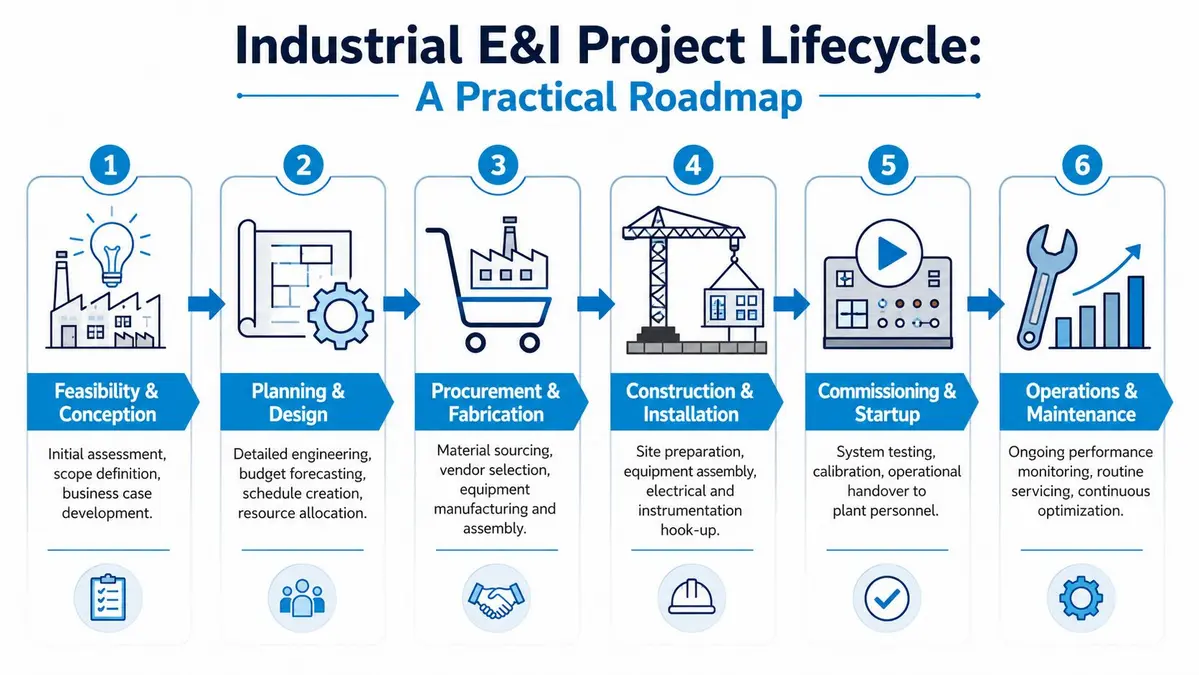
Source: cdnimg
Not every condition can be replicated in the factory. Product availability, site utilities, upstream and downstream equipment, and plant networks may limit the test. The FAT protocol should identify these limits clearly. The proper response is not to declare untested functions complete; it is to move them to a site-acceptance or commissioning test with an owner and acceptance criterion.
Stage 7: Treat commissioning as controlled verification
At the site, the commissioning lead should work from an agreed startup plan rather than a loose list of requests. The plan should sequence utility verification, network and interface checks, device checks, dry operation, integrated operation, product trials where included, and customer handover activities.
The commissioning team must also manage changes carefully. Field conditions can reveal genuine gaps: a different plant signal convention, an omitted interface, a mechanical adjustment affecting a sensor, or a customer operating requirement not fully captured earlier. Log the issue, assess its impact, obtain the appropriate approval, implement the change, and update the as-built information. Avoid treating a laptop-only edit as the final engineering record.
Commissioning technicians should not be pressured to bypass interlocks, defeat protective functions, or conceal unresolved faults to achieve a startup milestone. If a condition cannot be safely or functionally verified within the agreed scope, it should remain an open item with documented responsibility.
Build technician capability around the workflow
Technician training is most effective when it follows the actual work system. Training should cover reading released schematics, using diagnostic tools, panel inspection, point-to-point testing, PLC and HMI troubleshooting, software-change control, FAT execution, site documentation, and escalation rules.
A useful development path separates levels of authority. A junior technician may perform wiring checks and supervised I/O testing. An experienced technician may lead panel checkout and FAT execution. A senior commissioning technician may diagnose integrated systems and propose improvements. Engineering approval should still be required for changes that alter the released design, software architecture, safety-related behavior, component selection, or customer interface.
This structure does not diminish field expertise. It gives technicians a route to become stronger troubleshooters and reviewers without making them solely responsible for every engineering decision.
Close the loop after every project
The final stage gate is often missed: post-project review. Within a practical time after FAT or site acceptance, engineering, panel production, commissioning, service, and project management should review recurring issues.
Look for patterns such as repeated panel-layout conflicts, unclear drawing notes, frequent I/O errors, long software debug cycles, recurring alarms, difficult customer interfaces, or changes that repeatedly occur at site. Then assign each lesson to one of three destinations:
- Update the master design or code library.
- Update the build, FAT, or commissioning checklist.
- Update technician and engineer training.
The measure of a mature workflow is not that every project has no issues. It is that the same issue does not keep returning because knowledge stayed in an individual’s notebook, laptop, or memory.
A practical rollout sequence
OEMs do not need to redesign every legacy machine at once. Start with one machine family that has repeat volume, a manageable option set, and frequent startup pain. Define its standards, create a controlled master package, establish design-review and FAT gates, and track the changes found during build and commissioning. Once the process is stable, extend it to the next machine family.
The goal is a better division of labor: engineers create and govern the design system, builders produce to released information, technicians prove and commission the real machine, and every team contributes evidence that improves the next release. That is the foundation for more consistent food equipment, fewer avoidable field changes, and a more capable controls organization.
References
- Controls Engineer - FPEC | Food Processing Equipment …. (n.d.). https://fpec.com/careers/controls-engineer
- What’s the best practice for factory acceptance testing? | Control Design. (n.d.). https://www.controldesign.com/sensing/sensors/article/11300387/whats-the-best-practice-for-factory-acceptance-testing
- Factory Acceptance Testing (FAT): Process, Procedure & Checklist. (n.d.). https://www.dxpe.com/what-is-factory-acceptance-test-protocol-purpose
- Food Processing Equipment Controls Repair | Control Concepts. (n.d.). https://www.controlconceptstexas.com/food-processing
- The importance of independent Factory Acceptance Testing. (n.d.). https://www.saromglobal.com/why-factory-acceptance-testing-site-acceptance-testing-important
- PLC Commissioning Checklist: Step-by-Step Startup Guide. (n.d.). https://nexifyplc.com/plc-commissioning-checklist-step-by-step-startup-guide
- Top hmi software for industrial automation. (n.d.). https://www.facebook.com/instrumentation.control/posts/top-hmi-software-in-industrial-automation-read-the-full-guide-topic-hmi-software/1549305083885177