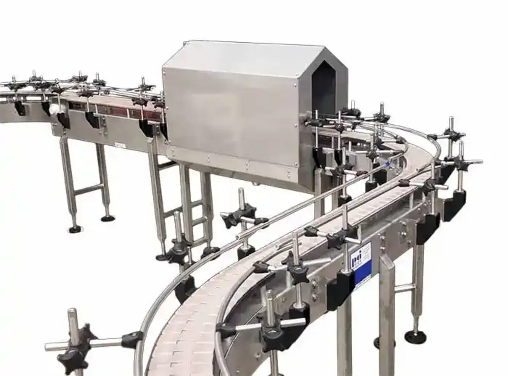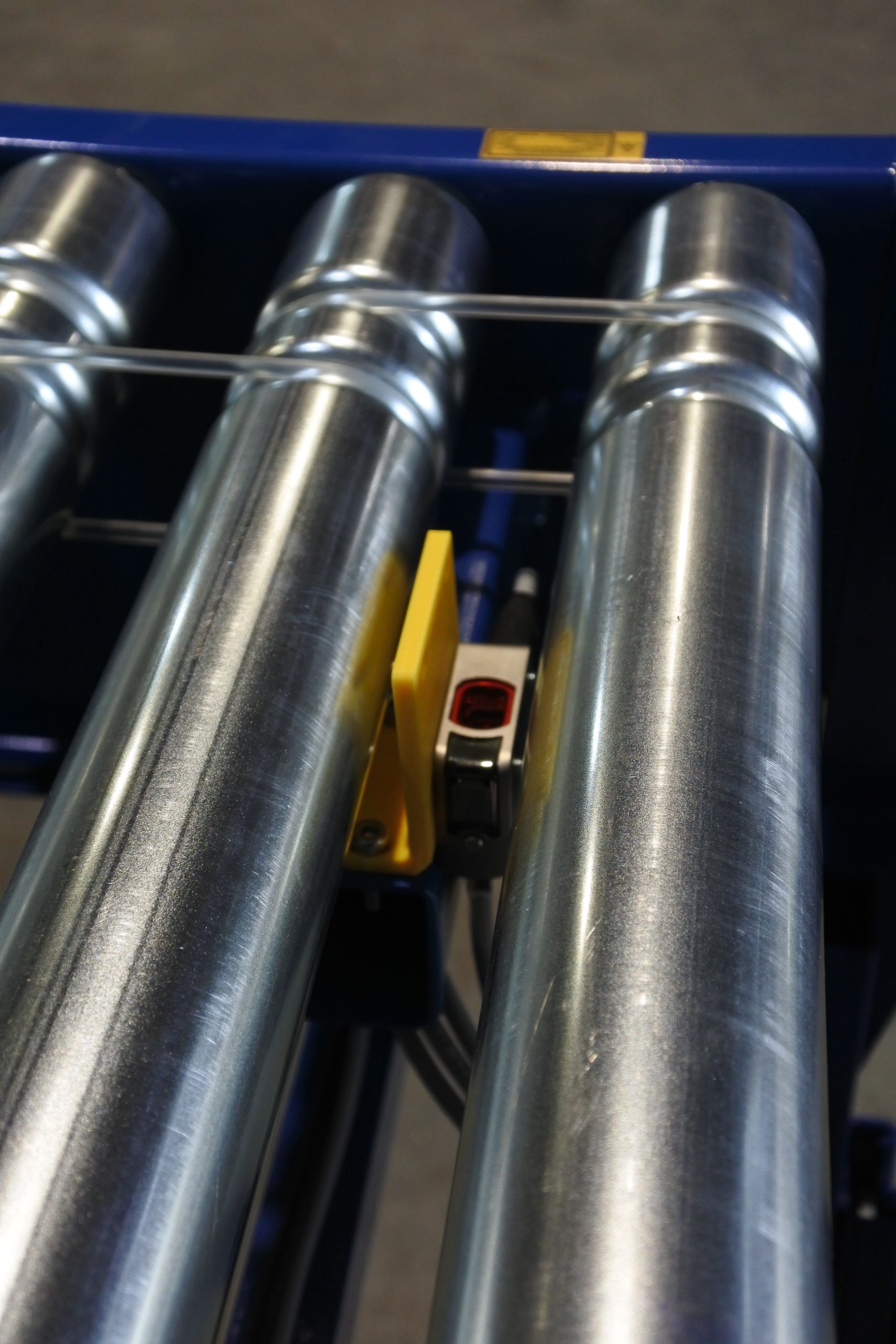
A sensor fault on a food line is not automatically a failed sensor. The same machine symptom—no product count, a stopped conveyor, a missed package, or a false reject—can come from contamination, target position, bracket movement, a damaged cable, low supply voltage, an incorrect PLC input condition, or the process itself.
The most effective food processing sensor troubleshooting method is to follow the signal path in a fixed order: confirm the machine condition, inspect the sensing application, verify power at the sensor, observe the sensor output, compare it with the PLC input, and then prove the repair. This sequence avoids the common mistake of replacing a sensor that was reporting a real mechanical or product problem.
Start with a safe, repeatable fault check
Before opening a connector or taking electrical measurements, follow the site’s electrical safety, machine isolation, sanitation, and lockout procedures. Do not bypass guards, defeat interlocks, force PLC inputs, or jumper a safety circuit to keep production moving. A sensor associated with personnel protection, safeguarding, or a safety-rated control function requires the plant’s approved safety troubleshooting process.
For ordinary process and packaging sensors, begin by recording what the machine is actually doing:
- What condition causes the fault: every cycle, only after washdown, at high speed, or only with a certain product?
- Is the failure a missed detection, a constant detection, a delayed signal, or an intermittent signal?
- Did work recently occur nearby, such as bracket adjustment, cable replacement, recipe changes, cleaning, or PLC work?
- Is the problem limited to one station or repeated across a group of sensors on the same power branch?
- What do the sensor status LEDs, PLC input indicators, and HMI diagnostics show at the time of failure?
A fault history often points to the correct category before a meter is used. For example, a fault immediately after washdown raises concern about water ingress, connectors, seals, or contamination. A fault that occurs only with darker film, irregular product, or a changed container finish is more likely an application or sensing-margin issue than a wiring break.
Understand the signal path before testing
Most machine-mounted DC sensors have four diagnostic points:
- The target or process condition being sensed.
- The sensor, including its power and output indicator.
- The cable and connector between the sensor and panel.
- The PLC input channel and control logic.
A useful rule is to compare each point with the next one. If the sensor output changes correctly but the PLC input does not, the sensor is usually not the first suspect. Focus on the connector, cable, terminal strip, input common, or input channel. If both the sensor indicator and PLC input change but the machine still behaves incorrectly, investigate PLC logic, timing, permissives, actuator feedback, or the mechanical process.
Step 1: Inspect the sensing application first
Many food plant sensor faults are false faults: the sensor is operating correctly, but the target is no longer reliably detectable. Start with the sensor face, target, bracket, and immediate environment.
Check contamination and physical damage
Look for product residue, film dust, oil, water, frost, label adhesive, or cleaning residue on optical lenses and proximity sensor faces. Inspect cable jackets, conduit entries, connector seals, and strain relief for cuts, crushing, loose coupling nuts, bent pins, or signs of moisture.
Clean only in a way permitted by the sensor manufacturer and the plant’s sanitation procedures. Abrasive cleaning can damage an optical window or degrade a seal. If a sensor is repeatedly contaminated, the durable fix may be shielding, relocation, an air purge where appropriate, or a different sensing method—not more frequent adjustment.
Check position, alignment, and stability
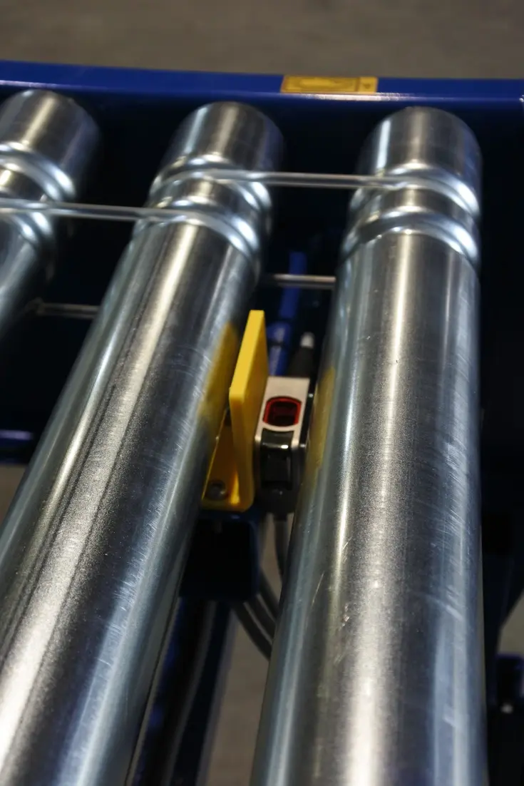
Confirm that the sensor is aimed at the correct target and that its bracket is secure. Vibration can gradually shift a photoelectric beam or reduce the gap between an inductive sensor and its target. Check for bent brackets, loose fasteners, conveyor tracking changes, and target movement during normal operation.
For photoelectric devices, identify the sensing mode before changing settings:
- Through-beam: verify transmitter and receiver alignment and ensure the beam path is clear.
- Retroreflective: inspect the reflector for contamination, damage, and alignment.
- Diffuse or background-suppression: verify the target’s color, surface finish, angle, and distance are within the intended sensing range.
For inductive proximity sensors, confirm that the target is the expected metal, has adequate area, and passes at a repeatable distance. Do not assume that a small, thin, moving, or differently shaped target will produce the same sensing margin as a larger reference target.
Source: conveyorsystems.co
Test with the real production condition
A hand-held test target can be useful, but it does not prove the application. Watch several normal cycles if safe to do so. A photoelectric sensor may respond to a white sample yet miss a dark, glossy, clear, wet, or irregular product. A proximity sensor may work when tested slowly but lose detection when a vibrating bracket changes the working gap.
Avoid immediately turning the sensitivity adjustment. First document the existing setting and confirm that contamination, alignment, target condition, and power are sound. Changing sensitivity too early can hide the original cause and create a later false-trigger problem.
Step 2: Verify 24 VDC sensor power at the sensor
Do not rely only on a healthy power-supply display or panel measurement. Measure at the sensor connector or the nearest accessible field termination, using approved test methods and the sensor’s wiring documentation.
Many industrial three-wire sensors use a DC supply commonly described as 24 VDC, but the allowed voltage range varies by model. Confirm the rating on the sensor label or data sheet. A supply can be acceptable at the control panel yet too low or unstable at the sensor because of a damaged conductor, loose terminal, undersized wiring, overloaded branch, or poor connection.
Check for these conditions:
- No voltage at the sensor: inspect fuses, branch protection, terminals, power distribution, and broken conductors.
- Voltage that drops when a load operates: investigate supply capacity, shared loads, loose connections, and voltage drop in the run.
- Intermittent power during vibration or washdown: inspect connectors, cable flex points, enclosure entries, and moisture paths.
- Reversed or incorrect wiring after replacement: compare every conductor with the specific sensor diagram rather than wire color alone.
On common DC sensor cables, brown is often supply positive and blue is often supply common, but colors are not a substitute for the manufacturer’s pinout. Verify the device and connector arrangement in use.
Step 3: Check sensor output state and logic
With power confirmed, present and remove the real target or simulate the condition in a controlled manner. Watch the sensor’s output LED. Many sensors also have a separate power LED, so verify what each indicator means for that model.
If the output indicator does not change when the target condition clearly changes, likely causes include poor alignment, an unsuitable target, contamination, insufficient sensing range, incorrect configuration, failed electronics, or a mechanical condition that is not what it appears to be.
If the indicator changes correctly, determine whether the output logic matches the machine expectation. Common mistakes include:
- A light-operate versus dark-operate selection that reverses expected behavior.
- A normally open versus normally closed logic mismatch in configuration or PLC programming.
- A replacement sensor set to a different mode from the original.
- A PNP sensor installed where an NPN output, or a differently wired input circuit, is required.
Do not diagnose PNP/NPN compatibility from sensor color or connector style. Confirm the sensor output type, PLC input module type, and input common wiring from the drawings and device documentation.
Step 4: Compare the sensor LED with the PLC input
This is often the fastest way to separate field-device faults from control-circuit faults.
| What you observe | Most likely area to investigate next |
|---|---|
| Sensor output LED does not change; PLC input does not change | Target, sensor condition, configuration, or sensor power |
| Sensor output LED changes; PLC input does not change | Connector, cable, terminal, input common, output compatibility, or PLC input channel |
| Sensor LED and PLC input both change; machine does not respond | PLC logic, timers, permissives, machine state, output device, or mechanical process |
| Sensor LED and PLC input both flicker | Unstable target, vibration, contamination, marginal alignment, or unstable supply |
| Sensor LED is stable; PLC input flickers | Field wiring, electrical interference, terminal connection, or input circuitry |
At the PLC, verify the correct input address. HMI labels, electrical drawings, and cabinet labels can be outdated after modifications. If the physical input LED changes but the program tag does not, the issue may be configuration, addressing, remote I/O communication, or logic rather than field wiring.
Where permitted by plant procedures, a qualified technician can use a known-good spare sensor or a documented test method to isolate the channel. Replacement should be like-for-like in sensing principle, supply range, output type, logic mode, connector pinout, environmental rating, and required response behavior.
Step 5: Inspect cables, connectors, and washdown exposure
Washdown sensor failures are frequently intermittent because moisture can enter a connector, damaged jacket, or poorly sealed cable entry and affect the circuit only under certain conditions. Examine areas that flex, rub, vibrate, or collect water: conveyor transitions, moving guards, cable supports, junction boxes, and low points in cable routing.
Look for greened terminals, water inside connector faces, cracked overmolding, pin damage, inadequate strain relief, and cable ties tightened hard enough to deform the cable. Also consider electrical noise where sensor leads share routes with variable-frequency drives, motors, solenoids, or high-current conductors. Correct routing, shielding, grounding, and separation should follow the machine design and sensor manufacturer guidance.
A cable that looks intact may still have an intermittent conductor. If the fault occurs during motion, carefully correlate the failure with cable movement or machine position while following safe work practices. Do not repeatedly flex a cable in a way that creates a hazard or damages it further.
Step 6: Prove the repair before closing the job
A replacement or adjustment is not complete when the fault message disappears once. Verify several normal cycles, including the operating conditions that originally created the problem: line speed, product variation, vibration, temperature, and post-cleaning conditions where relevant.
Record the failed symptom, the confirmed cause, the corrective action, sensor part number and configuration, and any changed settings. This matters when a recurring fault is really a design issue, such as an exposed cable route, an unstable mounting point, a target with weak contrast, or a sensor selected with too little application margin.
Common troubleshooting mistakes to avoid
- Replacing the sensor before checking whether it sees a valid target.
- Measuring power only at the control panel instead of at the sensor.
- Treating the sensor LED as proof that the PLC received the signal.
- Adjusting sensitivity before documenting the original setting and conditions.
- Installing a physically similar replacement without verifying output type and operating mode.
- Ignoring intermittent faults because the device works during a static test.
- Bypassing an input or interlock to run production.
When to escalate the fault
Escalate to qualified controls, electrical, machine-builder, or safety personnel when the issue involves safety functions, repeated electrical protection trips, damaged panel wiring, unknown modifications, PLC program changes, remote I/O faults, or a recurring condition that cannot be explained by the field device and process.
For routine food plant sensor faults, the key is disciplined comparison: process condition to sensor indication, sensor indication to PLC input, and PLC input to machine response. That simple chain usually identifies whether the fault is optical or mechanical, electrical, controls-related, or a genuine failed sensor.
References
- Sensor Troubleshooting: Diagnostics & Design Fixes. (n.d.). https://mechanical-design-handbook.blogspot.com/2026/08/industrial-sensor-troubleshooting.html
- Troubleshooting Industrial Food Processing Equipment. (n.d.). https://www.facebook.com/fb-answers/troubleshooting-industrial-food-processing-equipment
- Proximity Sensor Troubleshooting: Symptoms, Causes, and Testing. (n.d.). https://www.fabrico.io/blog/proximity-sensor-troubleshooting
- Photoelectric Sensor Troubleshooting: PLC Input Verification Guide. (n.d.). https://industrialmonitordirect.com/blogs/knowledgebase/photoelectric-sensor-troubleshooting-plc-input-verification-guide
- Industrial Proximity Sensor Test: 5 Proven Troubleshooting Steps. (n.d.). https://gtric.com/proximity-sensor-test
- Photoelectric Sensor Troubleshooting: 8 Fast Field Fixes. (n.d.). https://gtric.com/photoelectric-sensor-troubleshooting
- Why Proximity Sensors Fail Prematurely in Industrial Applications | Bedook®. (n.d.). https://www.bedooksensors.com/proximity-sensor-failure-causes
- How to Troubleshoot Photoelectric Sensors | Pantron Automation. (n.d.). https://www.pantron.com/us/articles.php?slug=troubleshoot-photoelectric-sensors