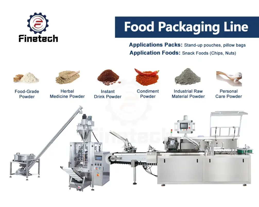
A successful food production line system design does not begin by selecting a mixer, filler, wrapper, or case packer separately. It begins by defining the product, the required output, and the operating conditions that every machine must support together. The finished line must transfer product and packages reliably, recover from normal stops, communicate through controls, receive adequate utilities, and have clear responsibility at every handoff.
The practical objective is a balanced system rather than a collection of individually capable machines. A high-speed packaging machine cannot create finished output if upstream processing cannot supply stable product, if changeovers take too long, or if downstream case handling regularly stops the line. Good design makes those dependencies visible before equipment orders and installation work begin.
Start with a line basis of design
The basis of design is the shared technical definition that prevents suppliers, operations teams, and contractors from working from different assumptions. It should be agreed before detailed quotations are compared.
At minimum, define:
- Product types, formulation range, physical condition, and permitted variation.
- Package formats, dimensions, weights or fill volumes, closure types, and labeling requirements.
- Required saleable output by product and package format.
- Planned operating schedule, including shifts, planned cleaning, changeovers, and expected downtime allowances.
- Product quality requirements at key process and packaging stages.
- Hygienic zoning, cleaning approach, drainage expectations, and access requirements.
- Site limits, including available floor area, ceiling height, column locations, access routes, and expansion constraints.
- Available electrical power, water, compressed air, steam, refrigeration, drainage, ventilation, and network infrastructure.
- Project boundaries: what is supplied by the equipment vendor, system integrator, facility contractor, and plant team.
The product definition needs more detail than a simple product name. For example, a viscous sauce, fragile baked item, powder, chilled prepared food, and free-flowing snack may all require very different transfer methods, buffering strategies, cleaning arrangements, and packaging equipment. Product temperature, viscosity, particle size, stickiness, fragility, and sensitivity to dwell time can determine whether an otherwise suitable machine arrangement will work.
Build the process flow before the equipment list
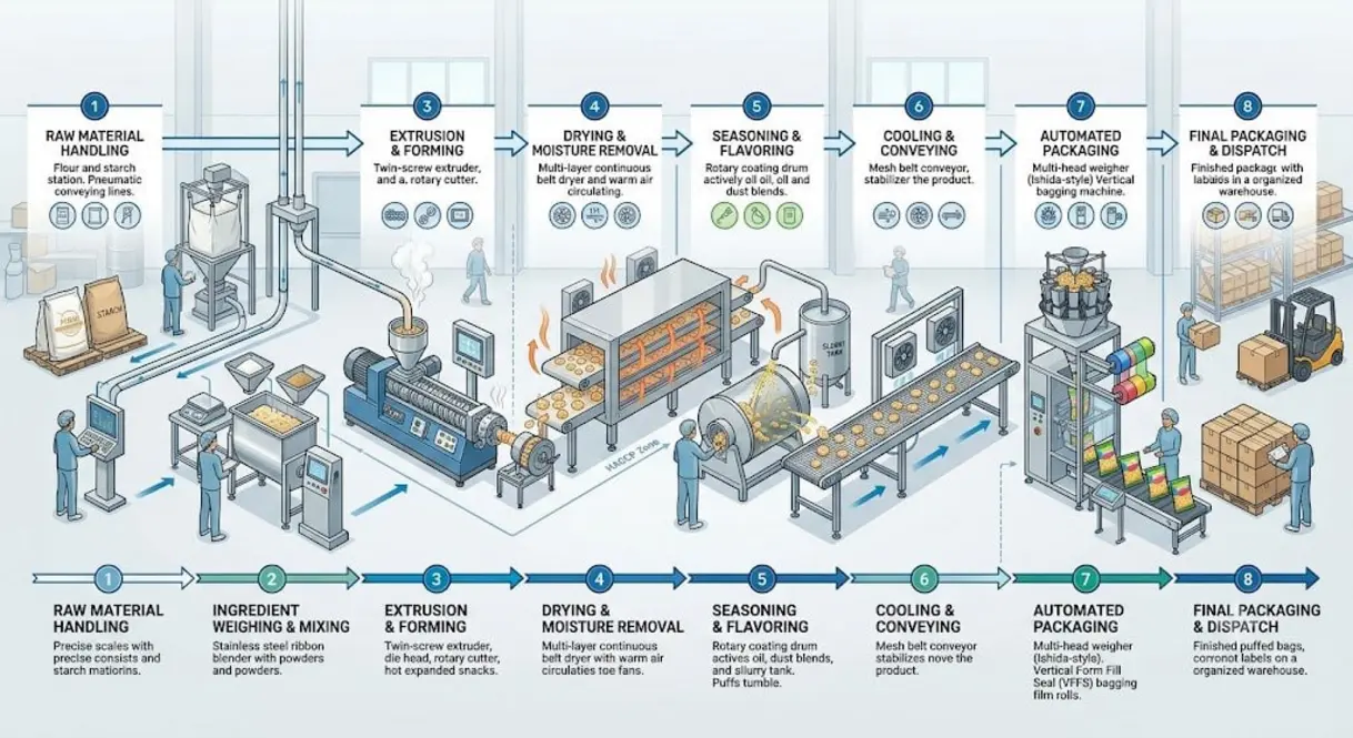
Develop a process flow that follows materials from receiving through finished-goods transfer. Each stage should have a defined purpose, inlet condition, outlet condition, normal operating rate, and control requirement.
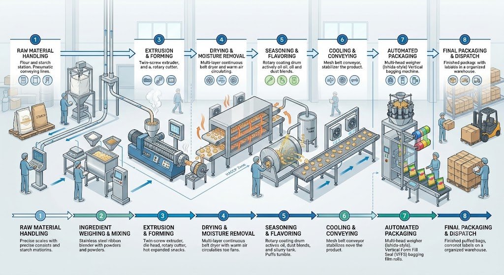
A typical high-level sequence may include:
- Ingredient receiving and storage.
- Weighing, batching, preparation, or thawing.
- Processing, such as mixing, cooking, forming, coating, cooling, or freezing.
- Product buffering or transfer to packaging.
- Primary packaging, such as filling, sealing, wrapping, or tray sealing.
- Inspection, coding, and rejection handling.
- Secondary packaging, including cartoning, case packing, or multipacking.
- Palletizing, finished-goods staging, and warehouse transfer.
For each step, establish what enters, what leaves, and what can happen when the next machine stops. This is where many food packaging line integration problems first become apparent. A cooker may continue producing product for a limited time after a filler stops. A filler may have a small internal buffer but no practical way to receive product after that buffer is full. A conveyor may move packs efficiently but offer too little accumulation to absorb a labeler or cartoner stoppage.
Source: zhuohengextruder
Calculate capacity as a system, not a nameplate rating
Machine nameplate speed is useful, but it is not the same as sustained line output. Food manufacturing line capacity design should consider the rate required at every stage, conversion losses, planned operating time, product variability, cleaning, changeovers, and normal minor stops.
Start with the required finished output over a defined production period. Then work backward through the line. Account for expected rejects, trim, giveaway where relevant, startup material, and any product that cannot be recovered after a stop. This produces a required operating duty for each upstream process.
A simple planning relationship is:
Required average rate = required good output ÷ available productive time
Available productive time should reflect the actual planned schedule, not the full calendar period. It is usually necessary to distinguish among:
- Peak machine rate: the short-term rate a machine can achieve under favorable conditions.
- Nominal operating rate: the expected rate under defined product and packaging conditions.
- Sustained line rate: the rate the complete installed system can maintain while handling expected interruptions.
The bottleneck is not always the machine with the lowest nominal speed. It may be a frequent manual task, a cooling limitation, a product transfer restriction, a package changeover, a downstream inspection device, or a utility limit. A line should be evaluated under realistic combinations of product, package format, staffing, and operating conditions.
Use buffers deliberately
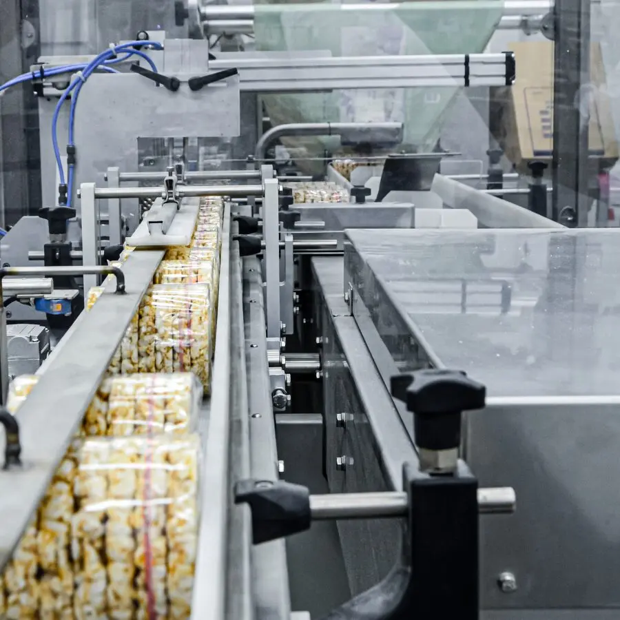
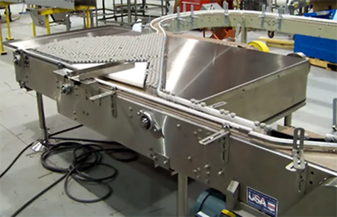
Accumulation is not simply empty conveyor length. It is controlled time between operations that behave differently during short stops, speed changes, or changeovers.
Buffers may be needed between continuous and intermittent equipment, between process and packaging areas, before inspection systems, or before secondary packaging. The correct amount depends on the stop pattern, product stability, package orientation, available space, and whether packages can safely accumulate without scuffing, deformation, mix-ups, or loss of traceability.
Too little accumulation creates stop-and-start behavior across the line. Too much can increase product exposure time, complicate cleaning, consume floor space, and make it harder to manage product identity during a fault or changeover. The design should state the purpose of each buffer and how it is controlled.
Source: multi-conveyor
Define every equipment interface
Production line equipment interfaces should be documented in an interface register, not left to informal coordination. Each connection should identify the supplying equipment, receiving equipment, physical handoff, operating limits, control relationship, and responsible party.
The table below shows the main interface categories to define.
| Interface type | Questions to resolve |
|---|---|
| Product or ingredient flow | What are the inlet and outlet locations, flow rate, temperature, pressure, viscosity, transfer method, and allowable hold time? |
| Package flow | What are the package orientation, transfer height, rail width, conveyor speed, accumulation behavior, and reject path? |
| Mechanical connection | Who supplies transition pieces, supports, guards, platforms, anchors, and access provisions? |
| Utilities | What utility is required, at what connection point, quality, pressure, flow, load, and operating condition? |
| Controls | Which machine commands start, stop, starve, block, speed-match, fault, or reset another machine? |
| Data and traceability | Which system owns production counts, lot data, recipes, code verification, alarms, and reporting? |
| Cleaning and hygiene | How are product-contact areas cleaned, drained, accessed, inspected, and protected during maintenance? |
| Safety and access | Who provides guarding at transfers, emergency-stop integration, safe access, and restart logic? |
A useful rule is that an interface is incomplete until it can be verified in a drawing, specification, signal list, or test procedure. Statements such as “supplier to connect to upstream equipment” are too vague unless connection details and responsibilities are defined.
Assign equipment responsibilities and scope boundaries
A coordinated line can involve process equipment vendors, packaging machine suppliers, conveyor providers, controls specialists, utility contractors, and plant personnel. Without a responsibility matrix, omissions often emerge late in installation.
For each system element, assign one accountable owner. Typical scope items that need explicit ownership include:
- Layout coordination and final line elevations.
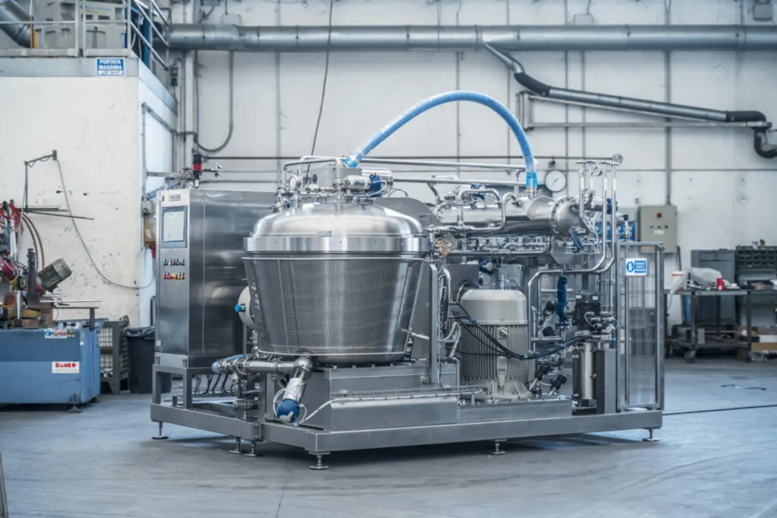
- Product piping, valves, pumps, and transfer skids.
- Conveyor transitions and package guides.
- Utility distribution from the facility connection to each machine.
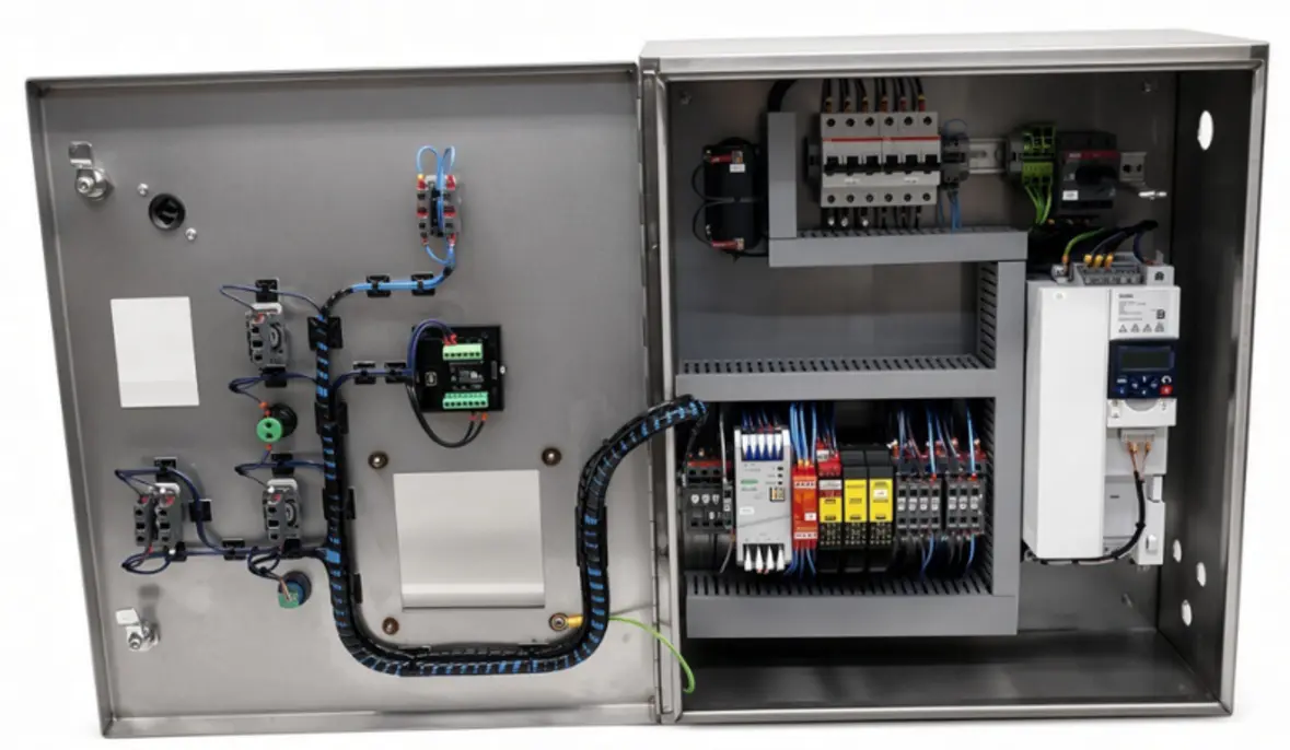
- Control panels, field wiring, network switches, and cable containment.
- Software integration, production data collection, and remote-access policies.
- Guards, access platforms, drains, and maintenance clearances.
- Installation supervision, startup support, training, documentation, and spare parts.
The project team should also identify who owns performance at the system level. Individual suppliers may demonstrate that their machines work independently, but line performance depends on the interaction of all supplied and site-provided elements. A system integrator may take that role, or the owner may retain it with a designated engineering lead. Either approach can work if the boundary is clear.
Design controls around operating states, not only signals
Controls integration should describe how the line behaves in normal running, starvation, blockage, fault, cleaning, changeover, restart, and emergency conditions. A signal list is necessary, but it is not enough by itself.
Define the expected behavior when a downstream machine stops. For example, upstream equipment may reduce speed, stop in sequence, divert product, or continue temporarily into a defined buffer. The correct response depends on product characteristics and process limits.
Key controls questions include:
- Which machine is the line master for speed coordination?
- How are upstream and downstream permissives established?
- What alarms are local, and what alarms must be visible on a line-level interface?
- Which equipment controls production counts and rejects?
- How are recipes or format settings transferred and verified?
- What reset sequence is required after a fault?
- How will operators distinguish a local machine issue from an upstream or downstream condition?
Avoid designing a line that requires operators to repeatedly bypass interlocks or make undocumented manual adjustments just to maintain flow. Recurrent manual workarounds usually indicate an unresolved interface, buffer, controls, or capacity issue.
Verify utilities, layout, and maintainability early
Utilities should be sized from the combined operating duty, including simultaneous loads and startup behavior where relevant. Confirm not only whether a utility exists but whether it is available at the required location, quality, and pressure or temperature range. Utility planning also needs to consider isolation, drainage, access for maintenance, and the effect of future expansion.
Processing and packaging equipment layout should support product flow, personnel movement, cleaning, material replenishment, waste removal, and safe maintenance access. A compact layout may reduce building area but can make changeovers, cleaning, troubleshooting, and service more difficult. Conversely, excessive spacing can create unnecessary transfer distances and operator travel.
Review the layout with operations, maintenance, sanitation, quality, engineering, and safety personnel before fabrication is finalized. Cross-functional reviews are especially useful for finding hidden conflicts around access, floor drainage, utility routes, guarding, allergen segregation, and material staging.
Commission in stages and test the integrated line
Factory acceptance testing can confirm that equipment meets agreed requirements that can reasonably be demonstrated before shipment. Site acceptance testing then addresses installed utilities, actual product and packaging materials, site controls, upstream and downstream interfaces, and site-dependent performance.
The acceptance plan should be written before the test, not created after commissioning begins. It should identify:
- Product and package formats to be used.
- Required operating conditions and utilities.
- Test duration and the definition of acceptable performance.
- Quality checks, reject handling, coding, and traceability requirements.
- Start, stop, fault, and restart scenarios to be demonstrated.
- Changeover and cleaning-related verification where included in scope.
- Data to be recorded, outstanding items, and responsibility for closure.
A useful commissioning sequence moves from individual equipment checks to dry line operation, then to integrated operation with representative materials and defined operating scenarios. Problems should be categorized by machine performance, interface design, installation, utilities, controls, incoming materials, or operating procedure. This helps avoid treating every failure as a single-vendor issue.
Common design mistakes to avoid
The most costly line problems often originate in assumptions that were never documented. Common examples include selecting equipment from maximum speed alone, leaving transfer pieces outside every supplier’s scope, assuming utilities are adequate without verification, and treating controls integration as an electrical task rather than an operating design task.
Other recurring mistakes include insufficient accumulation, no defined product disposition during stops, inaccessible equipment for cleaning or maintenance, and acceptance criteria that test machines separately but do not test the installed system as a whole.
A practical food production line system design turns those assumptions into visible requirements. When capacities, interfaces, controls, utilities, and ownership boundaries are defined early, the project team has a far better basis for comparing proposals, managing installation, and achieving stable production after startup.
References
- How to Engineer a Production Line for Food …. (n.d.). https://www.profoodworld.com/facilities-design-infrastructure/article/22927495/how-to-engineer-a-production-line-for-food-product-attributes
- Food Processing Line Design: How to Size and Specify Your Plant - SupplierTR. (n.d.). https://suppliertr.com/en/blog/food-processing-line-design
- How to Build a Food Production Line for Your Business. (n.d.). https://heysutton.com/blog/food-production-line
- What is a Packaging Systems Integrator?. (n.d.). https://krakenautomation.com/what-is-a-packaging-systems-integrator
- Complete Guide to Turnkey Food Production Line Setup 2025 - Uyarli Synergy. (n.d.). https://uyarlisynergy.com/turnkey-food-production-line-setup-guide-2025
- Designing Manufacturing Systems That Work Together. (n.d.). https://www.mix-sys.com/insights/process-and-packaging-solutions-integrated-manufacturing-systems
- A comprehensive guide to unifying food manufacturing planning | Black & Veatch. (n.d.). https://www.bv.com/perspectives/a-comprehensive-guide-to-unifying-food-manufacturing-planning
- Food Processing Equipment Factory Acceptance Test Guide. (n.d.). https://www.teemyeah.com/industry-news/food-processing-equipment-factory-acceptance-test