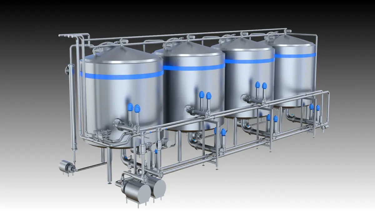
Legacy equipment can sometimes be made CIP compatible, but only when the product-contact surfaces can be reliably reached, cleaned, rinsed, drained, and verified without disassembly. The decision should begin with a documented food equipment cleanability assessment—not with the purchase of a CIP skid, spray ball, or automated valve.
A practical retrofit evaluates the complete cleaning path: how solution enters the equipment, contacts every internal surface, removes soil, returns to the CIP system, and leaves the equipment drained. If product-contact geometry, seals, internal mechanisms, or return piping prevent that sequence, a partial retrofit may create a false sense of security. In some cases, a combination of CIP and controlled clean-out-of-place or manual sanitation remains the sounder option.
Start with a cleanability assessment
Map the equipment as it actually exists in the plant. Original drawings are useful, but field modifications, replacement parts, instrument additions, and pipe reroutes often determine whether a CIP circuit will work.
Create a product-contact inventory for the machine and connected piping. Include tanks, pumps, heat exchangers, fillers, mixers, filters, flexible connections, valves, sample ports, sensors, drain points, and any internal assemblies. For each item, record:
- Product and soil characteristics, including whether residues are sticky, fatty, protein-rich, particulate, dry, or heat-set.
- Current cleaning method, disassembly requirements, recurring sanitation issues, and difficult-to-inspect areas.
- Materials of construction, surface condition, weld quality, gasket and seal materials, and component age.
- Existing CIP supply and return connections, if present.
- Available utilities, controls, drainage, chemical handling arrangements, and wastewater capacity.
- Parts that cannot tolerate the intended cleaning chemistry, temperature, flow, or pressure.
This inventory establishes whether the machine is a candidate for CIP retrofit food equipment work or whether its fundamental design requires replacement or routine disassembly.
Follow the intended CIP circuit from supply to return
CIP compatible equipment is not simply equipment with a spray device installed. It must be part of a complete, controllable flow path. Trace the proposed route from the CIP supply header to the equipment and back to the return line.
Ask four basic questions at every section of the route:
- Can cleaning solution reach the surface?
- Does it reach the surface with the required cleaning action?
- Can loosened soil and spent solution leave the area?
- Can the section drain after the cycle?
A “yes” to the first question is not enough. A branch may receive cleaning solution but still retain soil because flow is weak, a shadow area is present, or return flow is restricted.
Check supply flow and spray coverage
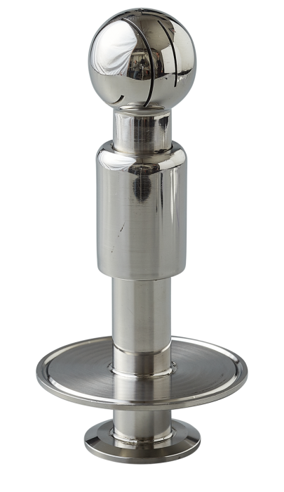
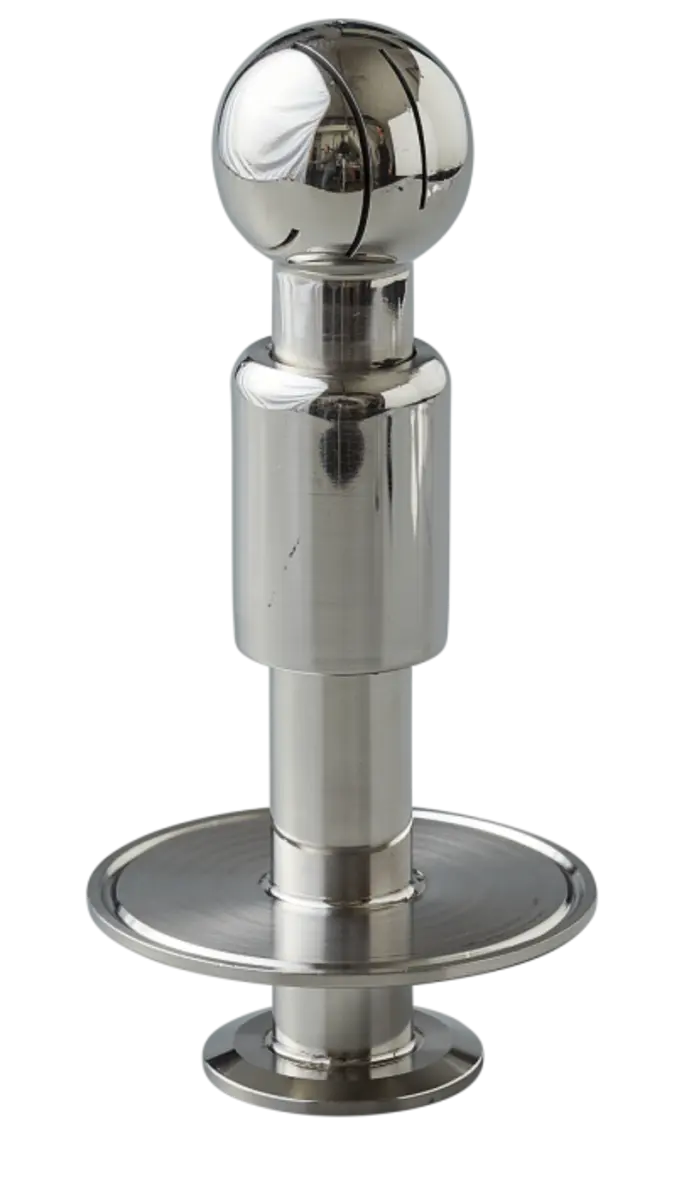
Tanks, hoppers, kettles, and enclosed mixers require a deliberate coverage review. Static spray devices, rotary spray devices, and other methods have different operating requirements. The device must suit the vessel size, internal geometry, soil type, and available flow and pressure.
Review internal obstructions such as agitator shafts, blades, baffles, manways, level probes, heating surfaces, and structural supports. These features can create shadow zones where solution does not adequately contact the surface. A retrofit may require a different spray device, added devices, changed orientation, or redesigned internals.
Do not assume a device will perform as expected because it fits a sanitary connection. Confirm its operating envelope with the manufacturer and compare it with the actual CIP pump curve, piping losses, elevation changes, and simultaneous circuit demand.
Source: glaciertanks
Evaluate piping, branches, and dead legs
Dead legs and stagnant branches are frequent barriers to clean in place equipment design. A branch that is poorly swept by flow can hold product or cleaning residue. Common examples include unused instrument ports, capped tees, sample valves, pressure taps, bypasses, and obsolete pipe stubs.
During the assessment, identify every branch off the principal process or CIP path. Determine whether it is necessary, whether it can be removed, and whether the remaining geometry can be adequately cleaned and drained. Eliminating an unused fitting is usually more dependable than trying to clean around it.
Also inspect field welds, transitions between pipe sizes, threaded or non-sanitary fittings, damaged surfaces, and crevice-prone joints. A CIP retrofit should correct accessible hygiene defects rather than automate cleaning around them.
Confirm drainability and CIP returnability
CIP returnability means the equipment can return cleaning solution, soil, and rinse water to the appropriate destination without trapping liquid or creating uncontrolled cross-connections. It is a system issue involving vessel outlets, pump behavior, piping slope, valve position, and return-line capacity.
Inspect whether tanks, lines, pump casings, and low points can drain in their installed orientation. Low pockets can retain product, water, chemical solution, or rinse water between cycles. Equipment that only drains when hoses are moved, fittings are opened, or the machine is tilted is not fully suited to unattended CIP.
Pay particular attention to:
- Pump housings and mechanical seals.
- Horizontal pipe runs with sags or poorly placed low points.
- Heat exchanger channels and bypass arrangements.
- Valve cavities and manifolds.
- Flexible hose sections and temporary connections.
- Filter housings, strainers, and inline instruments.
- Equipment with multiple outlets where one outlet becomes a stagnant pocket.
Return piping must also accommodate the expected flow without backing up into equipment. Return restrictions can reduce cleaning performance, interfere with tank spray patterns, or leave solution standing in the circuit. A qualified process or sanitary design engineer should confirm actual hydraulic behavior before installation.
Examine valves, seals, pumps, and internal mechanisms
Valves determine which circuits are cleaned and whether cleaning solution can enter unintended product paths. Review each valve for cleanability, seat and cavity design, drainability, actuator condition, and control feedback. At intersections between product and CIP circuits, the valve arrangement must prevent unintended mixing and allow the intended path to be cleaned.
Legacy manual valves can be suitable in limited applications, but they depend on correct setup and verification. Automated valves may improve repeatability, provided the valve matrix, controls, and maintenance program are designed for the process. A failed position indication or leaking seat can undermine both process separation and CIP execution.
Seals, gaskets, diaphragms, hoses, and pump elastomers need equal scrutiny. Verify compatibility with product, cleaning chemicals, and the planned operating conditions through the component manufacturer. Replace aged or damaged elastomers before validation; otherwise, a successful initial cycle may not represent long-term performance.
Equipment with rotating shafts, internal scrapers, fillers, conveyors, or complex moving parts deserves special attention. Some internal areas may not be reached by conventional CIP flow. Retrofitting may involve adding cleanable bearing arrangements, seal flush provisions, dedicated wash manifolds, or access for periodic inspection. If critical areas cannot be wetted, drained, and verified, retain a defined manual cleaning step rather than claiming full CIP capability.
Match instrumentation and controls to the cleaning risk
A CIP system retrofit needs enough instrumentation to demonstrate that each cleaning step occurred as intended. The exact instruments and acceptance criteria depend on the process, soil, cleaning program, and site food-safety plan, but typical monitoring points include flow, temperature, conductivity, level, valve position, and cycle time.
The goal is not to collect data for its own sake. It is to detect conditions that would make a cycle ineffective: inadequate flow, a missed valve position, insufficient cleaning solution concentration, unexpected dilution, poor return behavior, or a skipped sequence.
Review where sensors are installed and whether they represent conditions at the hardest-to-clean location rather than only at the CIP skid. Confirm that control logic handles abnormal conditions safely and records deviations for review. Do not use an automated record as a substitute for validation.
Prioritize retrofit work by risk and feasibility
After the survey, divide findings into three groups.
| Assessment outcome | Typical action |
|---|---|
| Easily corrected hygiene or flow issue | Remove unused branches, replace unsuitable fittings, improve drainage, repair welds, add appropriate connections or instrumentation. |
| Retrofit candidate with engineering work | Modify piping, valves, spray coverage, return lines, controls, or internal components, then validate the revised circuit. |
| Fundamental cleanability limitation | Keep controlled disassembly or COP steps, redesign the equipment, or replace it when reliable CIP cannot be demonstrated. |
Start with the areas that present the greatest product-contact risk and the weakest evidence of cleaning. The hardest-to-clean circuit should drive the retrofit design, not the simplest tank or shortest pipe run.
Validate before routine production use
Installation is not the end of the project. The processor must establish that the revised equipment and CIP cycle clean the intended surfaces consistently under normal operating conditions. The validation approach should be developed with the site food-safety team, equipment suppliers, chemical provider, and qualified sanitation or process specialists.
Validation should address the actual product soils, equipment configuration, cleaning sequence, and normal production conditions. It should also consider changeovers, allergen controls where applicable, maintenance states, and worst-case areas identified during the assessment. Use methods that are appropriate to the facility’s hazard analysis and verification program, and document both the rationale and results.
After validation, turn the retrofit into a controlled operating system:
- Maintain current piping and instrumentation diagrams.
- Lock down approved CIP recipes and access permissions.
- Train operators and maintenance personnel on valve lineups, inspections, and abnormal-condition response.
- Inspect spray devices, seals, valves, and return paths on a planned basis.
- Reassess the cleaning program when products, equipment, chemicals, production schedules, or piping change.
Common retrofit mistakes
The most common error is treating CIP as a utility connection rather than an equipment design requirement. Other avoidable mistakes include adding a spray ball without checking coverage, retaining obsolete branches, ignoring drainability, using manual valve lineups without reliable verification, and validating an easy circuit while overlooking complex equipment.
A useful CIP system retrofit makes cleaning more repeatable, but it cannot overcome inaccessible crevices, trapped liquid, unsuitable materials, or internal parts that are never contacted by the cleaning process. When those conditions remain, the correct decision may be a hybrid cleaning program or replacement of the limiting equipment.
For processors with legacy assets, the practical objective is not to label every machine CIP capable. It is to identify which equipment can be modified and validated for reliable automated cleaning, which needs controlled supplemental cleaning, and which design limitations are too significant to accept.
References
- CIP System Design & Installation for Food Processing. (n.d.). https://feeds.hixson-inc.com/blog/cip-systems-design-installation-food-industry
- CIP System Design & Installation for Food Processing. (n.d.). https://hixson-inc.com/feeds/blog/cip-systems-design-installation-food-industry
- Clean-In-Place (CIP) System | Korutek Engineering. (n.d.). https://korutek.com/clean-in-place-cip-system
- Sanitation in Food & Beverage Automation: CIP Systems. (n.d.). https://etechgroup.com/blog/general/make-cip-an-integral-part-of-your-process
- Sanitary Processing Equipment CIP Systems: FDA & BPE. (n.d.). https://www.marketbrief360.com/news/Intelligence_Dimension/ASME_BPE_FDA_Sanitary_Regs/How_Do_Sanitary_Processing_Equipment_CIP_Systems_Meet_FDA_and_ASME_BPE_Requirements.html
- Clean-in-Place (CIP) Systems for Food Processing | Blentech. (n.d.). https://blentech.com/2026/02/10/clean-in-place-cip-food-processing
- Clean in Place (CIP) in Food Processing | PMG Engineering. (n.d.). https://pmg.engineering/Article/14/clean-in-place-cip-in-food-processing
- CIP Cleaning: How to Ensure Food Safety Standards | Tractian. (n.d.). https://tractian.com/en/blog/cip-cleaning-how-to-ensure-food-safety-standards