A food conveyor encoder should be selected from the motion that actually matters to the process, not simply from the nearest rotating shaft. For repeatable stopping, indexing, cutting, labeling, sealing, transfers, and reject timing, first decide whether the control system must know drive-shaft rotation, actual belt travel, or the position of each product. Then match the encoder’s resolution, output signals, environmental protection, mounting method, and PLC input capability to that requirement.
In many applications, an encoder on the drive shaft is adequate and mechanically simple. It can be the wrong choice, however, when belt stretch, belt slip, lag at the drive pulley, or product-to-belt slip causes the actual product position to differ from calculated conveyor travel. A reliable food conveyor encoder selection process begins with defining the acceptable positioning error and identifying every source of motion between the encoder and the product.
Start with the positioning task
Write the application in operational terms before comparing encoder models. The required feedback for a carton indexing conveyor is different from the feedback for a continuous wrapper infeed or a simple reject conveyor.
| Application | What the encoder usually supports | Most important selection question |
|---|---|---|
| Indexing conveyor | Repeated move-and-stop positioning | Does feedback reflect actual belt movement at the stop point? |
| Continuous packaging infeed | Registration and speed synchronization | Can the encoder provide stable high-speed pulses to the motion controller? |
| Cutting or portioning | Cut timing relative to belt travel | Will belt or product slip create cut-position error? |
| Labeling or coding | Trigger timing and line-speed compensation | Is product detection also needed to establish the individual product position? |
| Reject conveyor | Tracking a product from inspection to reject point | Can the controller retain reliable position counts through speed changes and stops? |
| Transfer or merge | Handoff timing between conveyors | Which conveyor motion is the controlling reference during the transfer? |
An encoder measures rotation or position; it does not confirm that a product is present, centered, spaced correctly, or gripping the belt. Most product-tracking systems therefore combine encoder feedback with one or more photoelectric sensors, vision sensors, or machine signals. The sensor establishes a product event; encoder counts track its subsequent travel.
Choose where to measure motion
The mounting location is often more consequential than the encoder’s nominal resolution.
Drive-shaft measurement
Mounting an encoder directly to a gearmotor output shaft, driven pulley shaft, or conveyor drive shaft is common. It is compact, protected from contact with product, and generally easier to maintain than a wheel riding on the belt.
Use drive-shaft measurement when:
- The belt is positively driven or slip is not material to the process.
- Conveyor movement is tightly linked to shaft rotation.
- Positioning tolerance is modest relative to belt movement variation.
- The encoder is used primarily for speed feedback or synchronization.
- The application can re-home or re-register at regular intervals.
Its limitation is straightforward: the controller counts shaft rotation, not belt travel. A loose belt, worn drive surface, contamination, belt stretch, or transient slip can cause count error to accumulate between registration points.
Belt, roller, or tracking-wheel measurement
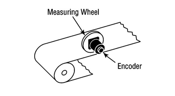
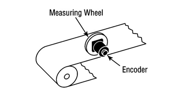
A measuring wheel, dedicated encoder roller, or encoder coupled to a non-driven roller can better represent actual belt motion. This approach is useful where belt travel rather than motor rotation determines the product position.
Use belt-motion measurement when:
- The conveyor uses friction drive and slip is a credible source of drift.
- Products must stop at a consistent station location.
- Cut, print, label, or inspection timing has a tight positional tolerance.
- The line has long runs where small errors can accumulate.
- Drive components may be changed without preserving the original reduction ratio.
A tracking wheel adds its own risks. It can slip on a wet or contaminated belt, lose contact as belt tension changes, and require careful spring loading and cleaning access. A roller-mounted encoder must also be assessed for bearing play, roller diameter variation, and any effect of belt tracking.
Source: dynapar
Product motion is a separate question
Even a perfectly installed belt encoder cannot compensate for products that slide, tumble, compress, or change spacing on the belt. For unstable products, establish position close to the downstream operation with a product sensor, or use a timing method that can re-register each item. On high-value applications, verify whether the process needs true product inspection or registration rather than a longer calculated conveyor track.
Incremental vs. absolute encoder conveyor feedback
For most conveyor tracking and speed-control duties, an incremental rotary encoder is the practical default. It produces pulses as the shaft rotates. The controller counts those pulses to calculate movement, and quadrature channels commonly allow direction detection. Encoder resolution is typically expressed as pulses per revolution (PPR), though the controller’s counting method may yield more usable count edges than the encoder’s basic PPR specification.
An incremental encoder suits:
- Continuous conveyor speed feedback
- Product tracking from a detection sensor to a downstream station
- Indexing systems that establish a home or reference position
- Packaging-machine synchronization where the controller continuously counts motion
The drawback is that incremental position is normally relative. After a power interruption, controller restart, missed pulses, or certain fault conditions, the system may need a homing or registration sequence before it can trust its calculated position.
An absolute encoder communicates a unique position value. Depending on the design, it may retain position through a power loss or report an absolute shaft position immediately at restart. It is worth considering when restart position matters, when a conveyor must recover without a full homing routine, or when the controller architecture already uses an absolute feedback network.
Absolute feedback does not eliminate mechanical error. If the encoder is mounted on a drive shaft while the belt slips, it will accurately report the wrong reference for actual belt travel. It also introduces protocol, controller, cable, and commissioning requirements that should be checked early.
Specify resolution from required linear accuracy
Do not select the highest PPR available by default. Higher resolution can improve the smallest measurable increment, but it also increases pulse frequency at speed and may exceed the capability of the PLC input, high-speed counter, motion controller, or cable installation.
Start with the conveyor’s effective measuring circumference:
linear travel per encoder revolution = roller or wheel circumference ÷ mechanical ratio
Then calculate the nominal linear increment:
linear increment per count = linear travel per encoder revolution ÷ usable counts per revolution
The resulting value is only the theoretical measurement increment. Actual positioning accuracy also includes belt behavior, roller runout, coupling backlash, shaft deflection, mounting movement, controller scan and response time, actuator repeatability, and product slip.
Specify resolution with margin, but avoid treating encoder count size as the entire accuracy budget. If a process cannot tolerate belt slip, moving from a moderate-resolution encoder to a much higher-resolution encoder will not solve the underlying problem.
Check pulse frequency at maximum speed
At maximum conveyor speed, encoder pulses may arrive quickly enough to overload a standard PLC input. Confirm all of the following with the controls supplier or machine documentation:
- Maximum encoder output frequency at top conveyor speed
- Maximum frequency accepted by the intended PLC input or high-speed counter
- Required counting mode and edge multiplication
- Input voltage, current, and signal thresholds
- Whether the controller needs single-ended or differential signals
- Cable length limits for the selected interface
- Whether the motion function requires a dedicated motion module rather than a general-purpose input
A system that works during slow manual operation may lose counts only at production speed. Those lost counts appear as random product-position drift.
Match the encoder to washdown and sanitation exposure
The enclosure rating must reflect the real cleaning zone, not only normal production conditions. Determine whether the encoder receives airborne moisture, foam, low-pressure rinse water, direct spray, or repeated high-pressure and high-temperature washdown. Also consider sanitizer chemistry, salt exposure, acidic products, and the likelihood of water collecting around a connector or shaft seal.
For direct high-pressure washdown, select an encoder and connector arrangement specifically rated for that exposure. IP ratings describe ingress resistance, but they do not by themselves confirm compatibility with every cleaning chemical, temperature condition, cable jacket, or mounting arrangement. Verify the complete installed assembly with the manufacturer: encoder housing, shaft seal, connector, mating cordset, cable, glands, and mounting hardware.
SICK describes an IP69K incremental encoder developed for frequent high-pressure chemical washdown in food and beverage environments, illustrating why washdown duty should be treated as a specialized selection requirement rather than an afterthought. See the manufacturer announcement.
Place the encoder away from the direct wash path where possible without compromising the measurement reference. Use hygienic mounting practices appropriate to the conveyor and sanitation program. Avoid brackets that trap soil or water, exposed crevices that cannot be cleaned, and cable loops that retain liquid. If a protective cover is used, make sure it can drain and can be removed or cleaned effectively.
Get mounting and coupling right
Encoder failures and drift are frequently mechanical installation problems.
A solid-shaft encoder should not be forced to compensate for shaft misalignment. Use a suitable flexible coupling where the application requires one, and align shafts carefully. A rigid coupling can transmit misalignment and vibration into encoder bearings or shafts. Conversely, an overly flexible or poorly secured coupling can introduce torsional windup and backlash.
Hollow-shaft or through-bore designs can simplify mounting directly on a conveyor shaft, but they still require correct shaft fit, anti-rotation restraint, and protection from excessive axial or radial loads. Check encoder documentation for allowable loads and mounting constraints.
During installation, inspect:
- Shaft runout and end play
- Drive pulley or roller bearing condition
- Bracket stiffness and vibration at operating speed
- Coupling alignment and set-screw security
- Clearance for cleaning and maintenance
- Protection from accidental impacts and product jams
- Whether service technicians can replace the encoder without changing the measurement ratio
A mechanically sound encoder can still produce poor tracking if the measured roller diameter changes due to wear, buildup, or a changed belt contact condition. Include these items in preventive inspection routines.
Plan wiring, shielding, and grounding before commissioning
Food plants often place conveyor motors, variable-frequency drives, contactors, solenoids, and encoder cables in close proximity. Electrical interference can distort pulse signals or create intermittent counts, especially on long cable runs.
Use the encoder manufacturer’s recommended cable type and connector system. Where noise risk is significant, differential line-driver outputs and shielded twisted-pair cable are commonly more robust than simple single-ended pulse wiring, provided the controller supports them.
Route encoder cable separately from motor leads, VFD output wiring, and high-current switching conductors where practical. Avoid long parallel runs with noisy power cables. Terminate shielding according to the encoder and controls documentation; grounding practices vary by signal type and system design, so an assumed shield connection can create as many problems as it solves.
Also verify that cable jackets and connector seals tolerate the washdown environment and cleaning chemicals. A high-rated encoder does not remain washdown-ready if its cordset, field connector, or cable entry is unsuitable.
A practical selection framework
Use this sequence when preparing a specification or reviewing an existing conveyor problem:
- Define the controlled event. Identify whether the encoder supports stopping, indexing, tracking, cut timing, label timing, transfer synchronization, or speed feedback.
- Set the usable positioning tolerance. Include the process station, actuator response, and product behavior—not only encoder counts.
- Choose the motion reference. Decide between drive shaft, driven roller, belt tracking wheel, or another direct measurement point.
- Identify re-registration points. Determine whether product sensors, homing switches, or packaging-machine registration marks can correct accumulated error.
- Calculate required resolution and maximum frequency. Confirm the controller can process the resulting signals at full line speed.
- Choose incremental or absolute feedback. Base this on restart behavior, controller architecture, and whether absolute position provides a real process benefit.
- Specify environmental protection. Account for washdown, chemicals, corrosion exposure, vibration, and connector orientation.
- Review mounting and cable routing. Treat bracket design, coupling alignment, shielding, and grounding as part of the encoder system.
- Validate on the running line. Test at normal and maximum speed, after washdown, during starts and stops, and across expected product and belt conditions.
Common causes of conveyor position drift
When a conveyor consistently stops short or long by a similar amount, begin with scaling: roller circumference, gear ratio, PPR setting, counter mode, and controller units. When error grows over distance, inspect slip, belt tension, measuring-wheel contact, and mechanical ratio assumptions.
Intermittent or seemingly random drift more often points to missed pulses, electrical noise, loose connectors, vibration, coupling movement, failing bearings, or unstable product movement. If the problem occurs after cleaning, inspect for moisture at connectors, cable damage, trapped water, seal degradation, and changed wheel-to-belt contact.
Do not compensate for unexplained drift solely by changing software offsets. An offset can correct a fixed station-location difference; it cannot correct a changing mechanical or electrical fault.
Commissioning checks after installation
Before relying on the encoder for automatic product positioning, validate the complete feedback path.
- Confirm encoder direction and count scaling against a measured conveyor movement.
- Run at low, normal, and maximum production speeds.
- Check repeatability over multiple index cycles and over a realistic operating period.
- Test normal starts, stops, speed changes, and controlled restart behavior.
- Verify that product sensors and encoder tracking remain aligned at the downstream station.
- Inspect actual pulse counts or diagnostic data for noise, dropouts, or unexpected count changes.
- Recheck performance after washdown and after any belt, roller, gearbox, or encoder replacement.
- Document controller parameters, mechanical ratios, encoder part details, cable type, and the validation result.
The right food conveyor encoder is therefore not just a device with a suitable PPR and enclosure rating. It is a feedback system matched to the conveyor’s real motion, the product’s behavior, the controls platform, and the sanitation environment. Selecting the measurement point first—and validating the installation under production conditions—does more for accurate positioning than simply choosing a higher-resolution encoder.
References
- Food Conveyors: A complete guide to making the right choice. (n.d.). https://mae-innovation.com/en/optimizing-your-production-line-with-the-right-food-grade-conveyor
- IP-Rated Rotary Encoders for Wet Environments | Sealed Encoder Selection – Industrial Monitor Direct. (n.d.). https://industrialmonitordirect.com/blogs/knowledgebase/ip-rated-rotary-encoders-selecting-sealed-encoders-for-industrial-applications
- Food-Grade Conveyor Systems: Sanitary, Washdown & USDA | PackagingConveyor.com. (n.d.). https://packagingconveyor.com/industries/food-conveyors
- Industrial Rotary Encoders: Selecting the Right Device for Your Application - Tech Briefs. (n.d.). https://www.techbriefs.com/component/content/article/28811-industrial-rotary-encoders-selecting-the-right-device-for-your-application
- Food-Grade Conveyor Components: FDA-Compliant Belting, Bearings, and Drives | IDI | IDI. (n.d.). https://www.int-dist.com/resources/food-grade-conveyor-components
- Food-Grade Conveyor System Design | Best Practices for Food …. (n.d.). https://fill-package.com/food-grade-conveyor-system-design-key-principles-and-best-practices
- SICK DEVELOPS FIRST IP69K INCREMENTAL ENCODER WITH ADDED INGRESS PROTECTION | SICK. (n.d.). https://www.sick.com/us/en/sick-develops-first-ip69k-incremental-encoder-with-added-ingress-protection/w/press-dbs60i-w
- Incremental Rotary Encoders. (n.d.). https://www.pepperl-fuchs.com/en/products/industrial-sensors/rotary-encoders/incremental-rotary-encoders-gp30138