Modbus RTU VFD control is usually a good fit when a PLC needs more than a simple run command: speed reference, current, frequency, fault code, operating status, and parameter access can all travel over one RS-485 network. It can reduce I/O count and field wiring substantially when several drives are distributed across a food or beverage line.
It should not automatically replace every hardwired signal. A practical food-processing design often uses Modbus RTU for normal operating commands and detailed status, while retaining selected hardwired signals for safety-related functions, local control, critical permissives, or straightforward maintenance diagnosis. The right split depends on the drive, the machine risk assessment, the production consequences of a communications fault, and the people expected to troubleshoot the line.
Start with the function, not the protocol
The useful question is not whether Modbus is better than wires. It is: what must this command do, what happens when it is lost, and how will a technician prove the cause of a failure?
Separate VFD functions into four groups before choosing the interface:
- Normal process control: run, stop, forward/reverse, speed setpoint, acceleration selection, and preset speeds.
- Process permissives and interlocks: downstream-ready signals, tank level conditions, valve positions, conveyor accumulation logic, product-flow conditions, and machine sequencing.
- Safety functions: emergency stopping, guard interlocks, safe torque off (STO), and other functions identified by the machine risk assessment.
- Maintenance and diagnostics: local/remote selection, hand control, reset authority, fault indication, motor current, run feedback, and communications health.
A drive may allow many of these functions to be assigned to terminals, keypad controls, or network registers. The available combinations are manufacturer- and model-specific. Confirm the exact control-source, fault-response, terminal-assignment, and communications parameters in the drive documentation before finalizing the panel design.
The three common architectures
| Architecture | Typical arrangement | Main advantage | Main limitation |
|---|---|---|---|
| Network-focused | PLC sends run, speed, and reset commands over Modbus RTU; drive status returns by registers | Low wiring count and rich diagnostics | Requires sound network design and less direct point-to-point diagnosis |
| Hardwired | Digital outputs provide run commands; analog output provides speed reference; discrete inputs return status | Familiar, visible, and simple to meter at terminals | More cable, I/O, and limited drive data |
| Mixed | Modbus handles normal commands and data; selected terminals handle local, permissive, or safety-related functions | Balances integration with practical maintenance access | Requires clear ownership of each function and careful parameter setup |
For a single pump with a simple speed requirement, hardwired run control and an analog speed reference may be entirely appropriate. For a conveyor zone with several drives and a central PLC, Modbus RTU can be a cleaner approach. For critical equipment where operations needs local control or maintenance needs an immediate field check, the mixed arrangement is often easier to live with.
When Modbus RTU is the better primary control method
Use network commands as the main normal-control path when the application benefits from the data available inside the drive.
Multiple drives share one machine or line controller
RS-485 allows a PLC to communicate with multiple addressed devices on a common serial network. This can reduce the number of individual conductors between a central panel and remote drives. On a long conveyor, washdown-area pump skid, or multi-motor process system, that reduction can simplify panel I/O and documentation.
The network must still be installed correctly. Cable type, routing, shielding practice, grounding approach, topology, termination, device addressing, and separation from motor leads should follow the PLC, drive, and cable manufacturer instructions. A VFD output cable can be a significant electrical-noise source, so communications wiring should not be treated as ordinary control wire.
The PLC needs detailed operating information
A hardwired fault relay can tell the PLC that a drive has faulted. Modbus can often report the active fault condition, output frequency, commanded speed, motor current, voltage-related information, digital-input state, operating mode, and other data supported by the drive.
That information helps distinguish between a process problem and a drive problem. For example, a pump may be commanded to run but remain at zero speed because of a permissive condition, local-control selection, a command-source mismatch, or a fault. Network data can narrow the investigation before a technician opens an enclosure.
Speed changes are frequent or recipe-driven
Modbus is useful where speed is tied to recipes, line states, product spacing, flow demand, or coordinated conveyor behavior. It avoids the scaling and signal-quality issues associated with an analog reference, provided that register mapping, data type, scaling, and command ownership are documented clearly.
Do not assume that a value written to a register produces the intended motor speed. Drives may use different register formats, scaling conventions, command words, and source-selection parameters. During commissioning, verify the actual reference, output frequency, motor rotation, and process response under controlled conditions.
When hardwired VFD control signals remain the practical choice
Hardwired control is not obsolete. It can be the clearest option where the function is simple and the failure mode needs to be diagnosed quickly with a meter and wiring diagram.
Simple, standalone equipment
A basic mixer, fan, pump, or conveyor may need only a maintained run permissive, start/stop logic, and one speed reference. In this case, adding serial communications may introduce configuration work without producing meaningful operational benefit.
Hardwired digital signals are also intuitive for many maintenance teams. A technician can check whether a PLC output changed, whether voltage reaches the drive terminal, and whether the drive input is configured correctly. That does not make the system inherently safer, but it can make routine troubleshooting more direct.
Local control must be obvious and controlled
Some equipment needs a clearly defined local operating mode for setup, maintenance, or recovery. This does not mean that a local selector or keypad should bypass required safeguards. It means local/remote authority, speed limits, permitted operation, and reset behavior should be designed deliberately.
A hardwired local/remote selector can provide an unambiguous indication of command authority. It can also prevent the PLC and a keypad from issuing competing run commands. Whether local operation is allowed, and under what conditions, should be established through the machine design and risk assessment.
A critical permissive benefits from an independent terminal signal
Certain process conditions may be easier to understand when they are directly represented at a drive terminal or interposing relay. Examples might include an external enable, a motor protection contact, or a machine-ready condition. The correct choice depends on whether the drive should act independently on that condition or whether the PLC must coordinate the response across the line.
Avoid creating duplicate, undocumented control paths. If a terminal input can prevent operation while the PLC displays a run command, the HMI, electrical drawings, and troubleshooting procedures should make that relationship clear.
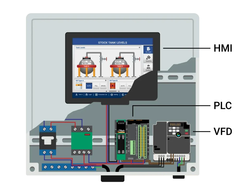
Source: media.maplesystems
Safety stopping is a separate design decision
Normal stop commands, whether sent over Modbus or a hardwired digital input, are not automatically safety functions. Modbus RTU is a general industrial communications protocol; it should not be assumed to provide a safety-rated stopping path.
Safety-related stopping, emergency-stop behavior, guards, restart prevention, and use of features such as Safe Torque Off must be determined by a documented machine risk assessment and implemented according to applicable requirements and the equipment manufacturers’ instructions. The drive’s STO inputs, external safety devices, contactors, and machine control system may each have a role depending on the required safety function.
Do not use ordinary network loss, a PLC stop command, or a standard fault relay as a substitute for a designed and validated safety function. Likewise, do not bypass STO circuits, guards, interlocks, or protective devices during troubleshooting. Qualified personnel should follow the site’s electrical safety procedures and lockout/tagout practices before work that exposes hazardous energy.
Design communications-loss behavior before commissioning
A networked drive needs an explicit response when valid Modbus messages stop arriving. Drives commonly provide communications-timeout settings and configurable actions, but the available options vary.
For each drive, decide and document:
- How the PLC detects a lost drive response.
- How the drive detects loss of PLC communications.
- The intended drive response: coast, controlled stop, hold last reference temporarily, fault, or another supported response.
- Whether the process can tolerate that response without causing product loss, mechanical problems, or unsafe conditions.
- Who can reset the resulting condition and what conditions must be met before restart.
There is no universal timeout value or fault action that fits every food line. A transfer pump, a screw conveyor, and a high-inertia mixer can have very different consequences when communications fail. Review the equipment behavior with process, maintenance, electrical, and safety stakeholders rather than selecting a default parameter without analysis.
A practical mixed-control pattern
For many food processing VFD controls, a useful architecture looks like this:
- Modbus RTU: normal run request, speed reference, drive status, current, frequency, fault code, and non-safety diagnostics.
- Hardwired signals: safety-related inputs where required by the safety design, a defined external enable or permissive where beneficial, local/remote selection, and perhaps a visible run or fault indication.
- PLC logic: sequence control, process interlocks, alarm handling, HMI indication, and a clear response to network faults.
- Drive parameters: command-source priority, reference-source selection, communications timeout, fault reset method, terminal assignments, acceleration/deceleration settings, and restart behavior.
This arrangement preserves the diagnostic value of network data without making every control function dependent on one communications path. It also gives maintenance staff physical reference points when troubleshooting, provided the drawings identify exactly what each terminal does.
Commissioning checklist for Modbus RTU VFD control
Before releasing the equipment to production, verify the system function by function.
- Confirm drive setup. Check that run commands and speed reference are assigned to the intended source: network, terminals, keypad, or a defined combination.
- Verify serial settings. Device address, baud rate, parity, data bits, stop bits, and register mapping must match the PLC configuration and drive documentation.
- Test normal commands. Prove run, stop, speed change, direction where applicable, and controlled process response.
- Test status feedback. Confirm that running state, ready state, fault state, actual frequency, and other selected values appear correctly at the PLC and HMI.
- Test command conflicts. Check what happens when local mode is selected, a terminal permissive is absent, or a keypad command is attempted.
- Test communications loss. Under an approved commissioning procedure, confirm that both PLC and drive respond as documented. Do not test safety functions by defeating protective devices.
- Verify restart behavior. Confirm that power restoration, fault reset, communications restoration, and mode changes do not create an unintended restart.
- Record final settings. Save drive parameters, PLC register maps, network addresses, cable routes, and troubleshooting notes in the machine documentation.
Troubleshooting priorities for a drive that will not run
When Modbus communications appear healthy but the motor does not start, first check command ownership. A drive can respond to register reads while still ignoring network run commands because it is configured for terminal or keypad control.
A structured check is usually faster than replacing hardware:
- Is the drive ready and free of an active fault?
- Is the PLC writing the expected control word and speed reference?
- Does the drive show the expected command source and reference source?
- Are any hardwired enables, permissives, or local/remote selectors blocking operation?
- Is the drive receiving a valid network message within its configured timeout?
- Is the network address unique and are serial settings consistent across devices?
- Are termination, shield connection, cable routing, and RS-485 polarity installed as specified?
- Does the drive’s actual status indicate a process interlock, external input, safety function, or internal fault condition?
For hardwired functions, use current drawings and approved electrical test practices to verify the signal at the PLC output and at the drive terminal. For network functions, compare the PLC’s transmitted value, the drive’s received command indication, and the actual operating state. That three-point comparison often identifies whether the issue is in PLC logic, communications, drive configuration, or the process interlock.
Selection mistakes to avoid
The most common mistake is treating all stop functions as equivalent. A normal production stop, a controlled process stop, a drive fault response, and a safety-related stop have different purposes and should not be assigned to a protocol simply because it is convenient.
Other avoidable mistakes include relying on undocumented default drive parameters, allowing multiple command sources without a priority plan, disabling communications timeout during commissioning and leaving it disabled, and omitting clear drawings for mixed architectures.
Choose Modbus RTU VFD control when its data and reduced wiring solve a real operating problem. Keep hardwired VFD control signals where they improve local clarity, provide a defined independent permissive, or support the required machine design. In food processing, the strongest approach is often not network-only or wire-only, but a documented division of responsibility that operators and maintenance teams can understand on a production shift.
References
- Control a VFD Using its Built-in Modbus RTU Port. (n.d.). https://www.youtube.com/watch?v=TmqzhsfcMHQ
- Modbus RTU control of VFD : r/PLC. (n.d.). https://www.reddit.com/r/PLC/comments/1lytogp/modbus_rtu_control_of_vfd
- Is Fieldbus Less Reliable Than Hardwired Control for VFDs?. (n.d.). https://waywardleaders.com/field-notes/f/is-fieldbus-less-reliable-than-hardwired-control-for-vfds
- PLC-VFD Communication: Hardwired vs Modbus | Ekweme Precious posted on the topic | LinkedIn. (n.d.). https://www.linkedin.com/posts/ekweme-precious-64028930b_insightful-comparison-on-plcvfd-communication-activity-7407743672810717184-FpRk
- Control a VFD Using its Built-in Modbus RTU Port - Horner Automation. (n.d.). https://hornerautomation.eu/aiovg_videos/control-a-vfd-using-its-built-in-modbus-rtu-port
- VFD Communication Fault: Modbus, RS-485 & Fieldbus Fixes. (n.d.). https://eilitetech.com/vfd-communication-fault
- Control a VFD Using its Built in Modbus RTU Port - YouTube. (n.d.). https://www.youtube.com/watch?v=-1shY1d3z64
- Difference between Modbus and Fieldbus. (n.d.). https://www.amissiontech.com/news/difference-between-modbus-and-fieldbus.html