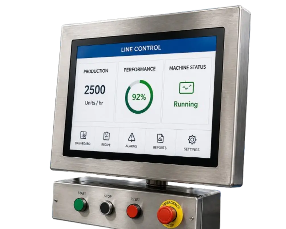
Good PLC diagnostics for food packaging lines let an operator or maintenance technician answer four questions without immediately connecting programming software: What state is the machine in? What is preventing the next action? Which device or condition caused the stop? What is the approved recovery sequence?
That requires more than an alarm banner and a reset button. The HMI, PLC program, drives, remote I/O, and machine sequence should present the same diagnostic story. A well-designed system exposes the active fault, the first condition that failed, the relevant permissives, live device feedback, and a practical next check. This reduces avoidable escalation while keeping safety functions and authorized maintenance work separate from routine recovery.
Start with a diagnostic model, not an alarm list
An alarm is only one part of a machine diagnostic system. Packaging equipment often stops because of a sequence dependency: a guard circuit may be open, a downstream conveyor may not be available, a product-present sensor may be blocked, a servo may not be ready, or a cylinder may not have reached its commanded position in time.
If the HMI reports only “Machine Fault” or “Station 4 Error,” the user still has to search electrical drawings, inspect the machine, or connect online to the PLC. Instead, build diagnostics around the machine’s operating model:
- Machine mode: Off, manual, setup, automatic, stopping, faulted, or safety stopped.
- Current sequence state: The active step and the next expected action.
- Permissives: Conditions required to start or continue a sequence.
- Fault detection: The specific condition that failed, including timeouts and contradictory feedback.
- Recovery: The checks, acknowledgments, and commands permitted for that condition.
- History: A timestamped record that helps distinguish a one-time obstruction from a repeating issue.
This approach reflects a central troubleshooting reality: the visible symptom may not be the root cause. A command can be active while a physical device does not respond, and one subsystem may appear ready while another remains inhibited. The diagnostic design must make those distinctions visible.
Define machine states clearly
The top level of every machine troubleshooting screen should show a plain-language operating state. Avoid ambiguous labels such as “Not Ready” when the user needs to know whether the machine is waiting, inhibited, stopping normally, or faulted.
A practical state model may include:
| HMI state | What it means | What the user needs to see |
|---|---|---|
| Safe stop | A safety-related condition is preventing motion | Safety status and the area or device requiring attention, where available |
| Faulted | A control, device, drive, or process fault has stopped the sequence | First-out fault, active faults, and reset conditions |
| Start inhibited | No fault is latched, but a start permissive is missing | Individual missing permissives |
| Waiting | The machine is running its sequence but waiting for an expected condition | Current step, expected feedback, and elapsed wait time |
| Running | Automatic sequence is active | Current recipe or format, station status, and major production conditions |
| Manual/setup | Authorized manual functions may be available | Active mode, restrictions, and manual device feedback |
Keep safety diagnostics distinct from standard control diagnostics. The HMI can indicate that a safety condition is active, but it should not encourage operators to defeat guards, bypass interlocks, or use maintenance functions outside the plant’s approved procedures. Recovery from a safety stop should follow the machine’s documented safeguarding design and site rules.
Build alarms that identify the condition and the action
A useful alarm tells the user what happened, where it happened, and what to check first. It does not need to diagnose every possible electrical cause, but it should eliminate vague searching.
Compare these messages:
- Poor: Conveyor error
- Better: Discharge conveyor did not reach run feedback after start command
- Better with guidance: Discharge conveyor did not reach run feedback after start command. Check drive ready status, local disconnect, overload indication, and conveyor obstruction.
Alarm text should be based on the actual logic condition. If the PLC detects that a motor command is on but no running feedback arrives before a timeout, say that. Do not label it “motor failure” unless the machine can truly establish that conclusion.
For each alarm, define an alarm record during design or commissioning:
- Unique alarm ID
- Short display name
- Detailed message
- Priority appropriate to its operational consequence
- Trigger condition and reset condition
- Whether it is latched or self-clearing
- First checks for the operator
- Escalation point for maintenance
- Related HMI page or device faceplate
Alarm rationalization is especially important in food plants, where packaging machines, CIP activity, refrigeration, and process equipment can create a high volume of annunciations. An alarm flood makes it harder to identify the condition that actually stopped production. Guidance on alarm management, including the ISA-18.2 framework, emphasizes a structured process covering alarm philosophy, identification, rationalization, design, operation, maintenance, and performance monitoring. PLC Programming’s overview of HMI alarms, events, and trends provides a useful introduction to that lifecycle.
Show permissives as a checklist, not a generic “not ready” message
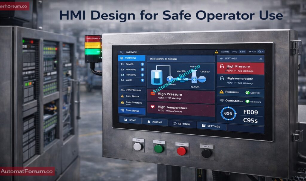
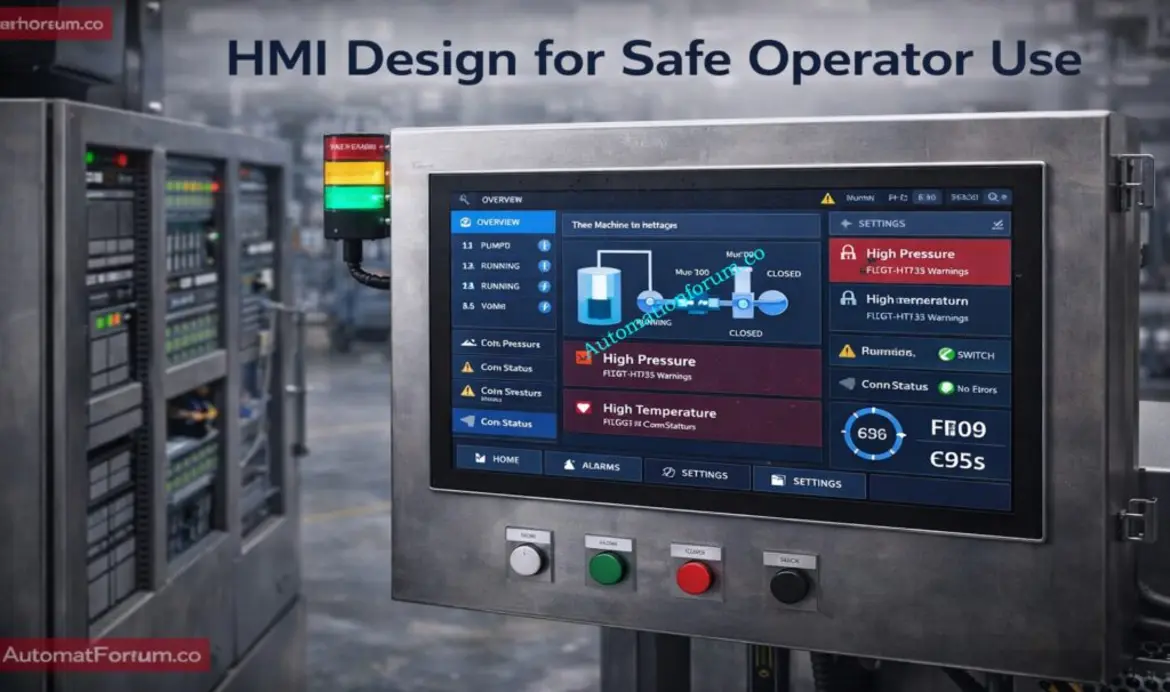
Permissive screens are one of the most valuable features in operator-friendly PLC programming. They show the conditions the PLC requires before enabling a machine, module, motor, or sequence step.
Source: cdn.automationforum
For example, a carton sealer start permissive page might show:
- Safety system healthy
- Automatic mode selected
- No active station fault
- Compressed-air condition available, if monitored
- Drive ready
- Infeed conveyor available
- Discharge path available
- Carton present or product conditions met, when applicable
- Guarded access area clear, where represented by the safety system
Use a green/red or true/false presentation with a descriptive label. Avoid unlabeled bit indicators and engineering tag names. “XIC_Station4_OK” may be useful in the PLC program, but “Sealer cylinder home position not confirmed” is useful on the HMI.
For nested logic, let users drill down. A top-level permissive such as “Discharge available” should link to the downstream equipment conditions that make it false. This prevents the common pattern of opening several screens to find a single missing signal.
If a maintenance bypass exists by design, display it prominently wherever it affects operation and record its status in the event history. Bypasses should remain controlled by the machine’s risk assessment, site procedures, and authorized access design; they are not a general-purpose troubleshooting tool.
Use device faceplates to compare command, feedback, and health
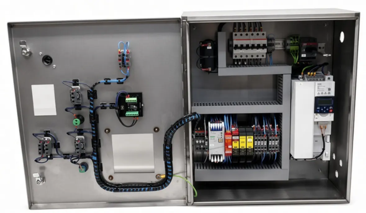
A device status screen should answer whether the PLC is trying to operate a device and whether the device is responding. This is essential for motors, VFDs, servo axes, pneumatic valves, cylinders, sensors, and remote I/O points.
Source: cdn.shopify
For a motor or conveyor drive, show at least:
- Commanded state: start/stop or speed command
- Feedback state: running, at speed, faulted, or unavailable
- Drive ready indication
- Active drive fault code or text when available
- Hand/off/auto or local/remote status, if applicable
- Relevant permissives and interlocks
For a pneumatic cylinder or actuator, show:
- Extend or retract command
- Home and extended sensor feedback
- Expected position
- Timeout status
- Last completed motion, if retained
For a photoelectric sensor, show its live input state, a readable device name, and the role it plays in the sequence. A technician can then determine whether the PLC sees the sensor change without opening the PLC project. This does not replace field inspection: a correct input indication does not prove that the mechanical process is functioning correctly.
Add fault guidance at the point of use
The best PLC fault recovery guidance is brief, condition-specific, and linked directly from the alarm. Avoid a generic troubleshooting manual buried in an HMI menu.
A fault guidance panel can include:
- What the PLC detected: “Infeed product sensor remained blocked during transfer timeout.”
- Likely physical area: “Inspect infeed transfer between accumulation conveyor and wrapper infeed.”
- Safe first checks: “Remove product obstruction using approved methods; inspect sensor lens and alignment; confirm conveyor motion.”
- Reset requirement: “Clear condition, acknowledge alarm, then request reset.”
- When to call maintenance: “If sensor state does not change, conveyor does not run, or the fault repeats.”
The wording should match user roles. Operators need normal recovery steps and clear boundaries. Maintenance personnel may need deeper details: I/O channel, electrical drawing reference, drive diagnostic value, device tag, or network node. A role-based HMI can reveal this extra detail without filling the standard operator screen with information that does not help normal recovery.
Preserve the first-out event and sequence context
In packaging equipment, a single obstruction can trigger many secondary alarms. A jam may cause a sensor timeout, then a station timeout, then a downstream not-ready condition. If the annunciator displays every resulting alarm with equal emphasis, the initiating event disappears.
Capture and retain a first-out fault for each stop cycle. Present it separately from the list of currently active alarms. Also retain useful sequence context:
- Machine state when the stop occurred
- Active recipe or format
- Current station and sequence step
- Commanded device state
- Relevant feedback values
- Time since the sequence step began
- Operator action, reset, or mode change
Event history should record when alarms become active, clear, and are acknowledged. It should also log consequential state changes such as automatic mode selection, reset requests, safety status changes, drive faults, communication losses, and authorized bypass activation. Time synchronization across the HMI, PLC, drives, and supervisory systems matters; otherwise, event order becomes difficult to reconstruct.
Design PLC logic for diagnostic quality
HMI quality depends on PLC program structure. If permissives, commands, feedbacks, fault latches, and sequence states are mixed into large, undocumented logic networks, creating reliable diagnostic screens becomes difficult.
Organize reusable equipment modules around consistent data:
- Command inputs
- Field feedbacks
- Permissives
- Interlocks
- Fault conditions
- Alarm codes and text references
- Timers and timeout status
- Device mode and availability
- Reset eligibility
Use standardized naming and a consistent state model across similar stations. A wrapper infeed conveyor, cartoner discharge conveyor, and case packer transfer conveyor may differ mechanically, but their diagnostic pattern should be familiar: command, ready, run feedback, fault, blocked permissive, and timeout reason.
Network diagnostics deserve the same discipline. A lost remote I/O rack, drive, HMI, or controller connection should identify the affected node or segment rather than producing only a general communications alarm. Industrial network failures can stop machines through unavailable sensors, drives, or remote devices, so the diagnostic page should distinguish a device fault from a communications fault where the system can do so.
Validate diagnostics during commissioning and after changes
Do not consider a diagnostic feature complete because the alarm text appears on the screen. Test each expected failure mode in a controlled commissioning process and confirm that the HMI leads a user to the relevant condition.
A practical validation checklist includes:
- Confirm every alarm message matches its actual trigger.
- Verify the first-out fault remains visible after secondary faults occur.
- Test missing permissives one at a time.
- Check that a device screen distinguishes command from feedback.
- Confirm fault guidance does not instruct users to bypass safeguards.
- Verify event timestamps and order across connected systems.
- Review what happens when communications to a drive, remote I/O island, or HMI are lost.
- Test recovery after normal jams, product changeovers, power restoration, and controlled stop conditions.
- Ask operators and technicians to use the screens during acceptance testing, then revise unclear wording.
Recurring downtime should feed back into the diagnostic design. If maintenance repeatedly goes online to find the same missing input, unclear interlock, or drive status, that evidence belongs in the HMI. The goal is not to expose every PLC variable. It is to provide enough accurate, contextual information for common faults to be identified, corrected, and verified at the machine—while preserving a clear handoff to qualified personnel when deeper control, electrical, network, or safety investigation is required.
References
- Industrial Automation Troubleshooting: PLC, HMI, SCADA, Drives, Networks and Control-System Diagnostics (Industrial Troubleshooting) | mitpressbookstore. (n.d.). https://mitpressbookstore.mit.edu/book/9798187460823
- HMI Alarms, Events and Trends: Design and Troubleshooting. (n.d.). https://plcprogramming.io/guides/hmi-alarms-events-trends
- PLC Troubleshooting Guide: Common Issues, Solutions & Maintenance Tips. (n.d.). https://mfgtechhub.com/plc-troubleshooting-guide
- PLC Communication Failure Troubleshooting (Industrial Network & PLC…. (n.d.). https://machinematcher.com/knowledge/plc-communication-failure-troubleshooting-industrial-network-plc-diagnostics-guide
- Alarm Management in Food and Beverage Plants. (n.d.). https://ifactoryapp.com/article/food-plant-alarm-management
- PLC permissive logic troubleshooting guide for industrial …. (n.d.). https://www.facebook.com/instrumentation.control/posts/plc-permissive-logic-troubleshooting-procedure-read-full-guide-topic-plc-permiss/1510071684475184
- PLC Troubleshooting: A Step-by-Step Guide for Maintenance …. (n.d.). https://itclearning.com/blog/plc-troubleshooting
- PLC Permissive Logic Troubleshooting Procedure – Step-by-Step Guide. (n.d.). https://automationforum.co/plc-permissive-logic-troubleshooting-procedure