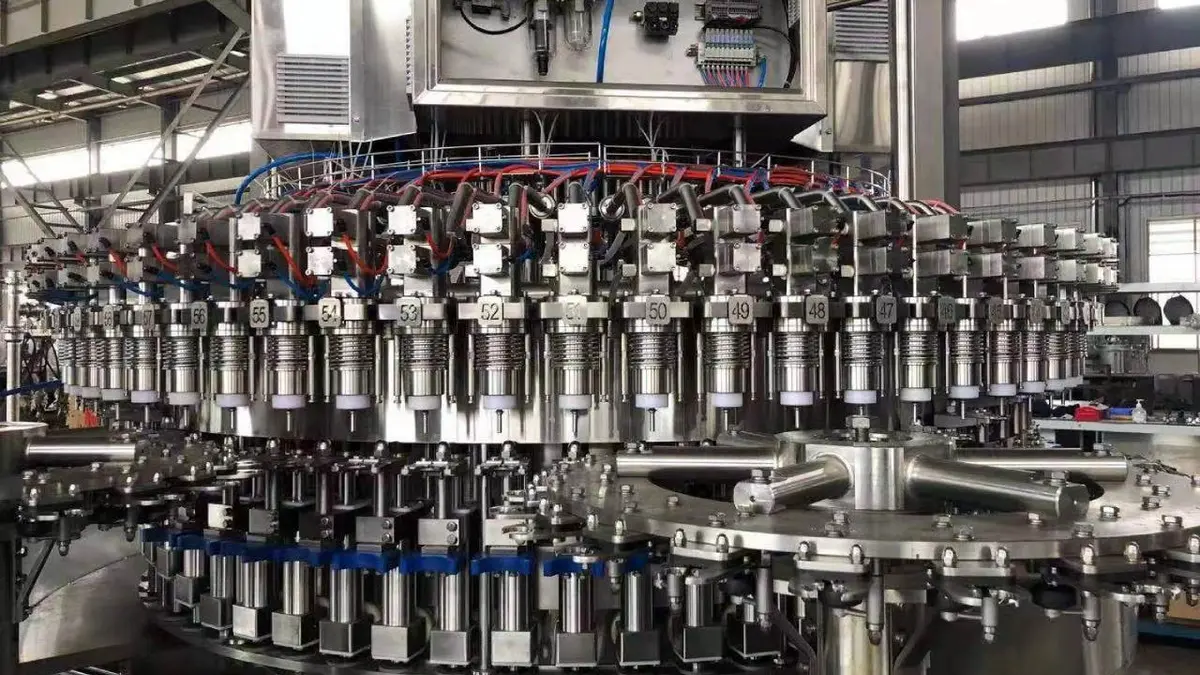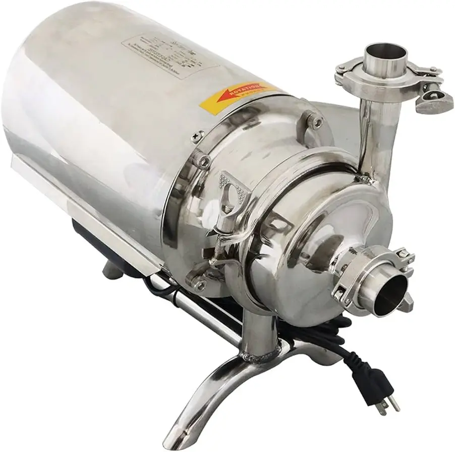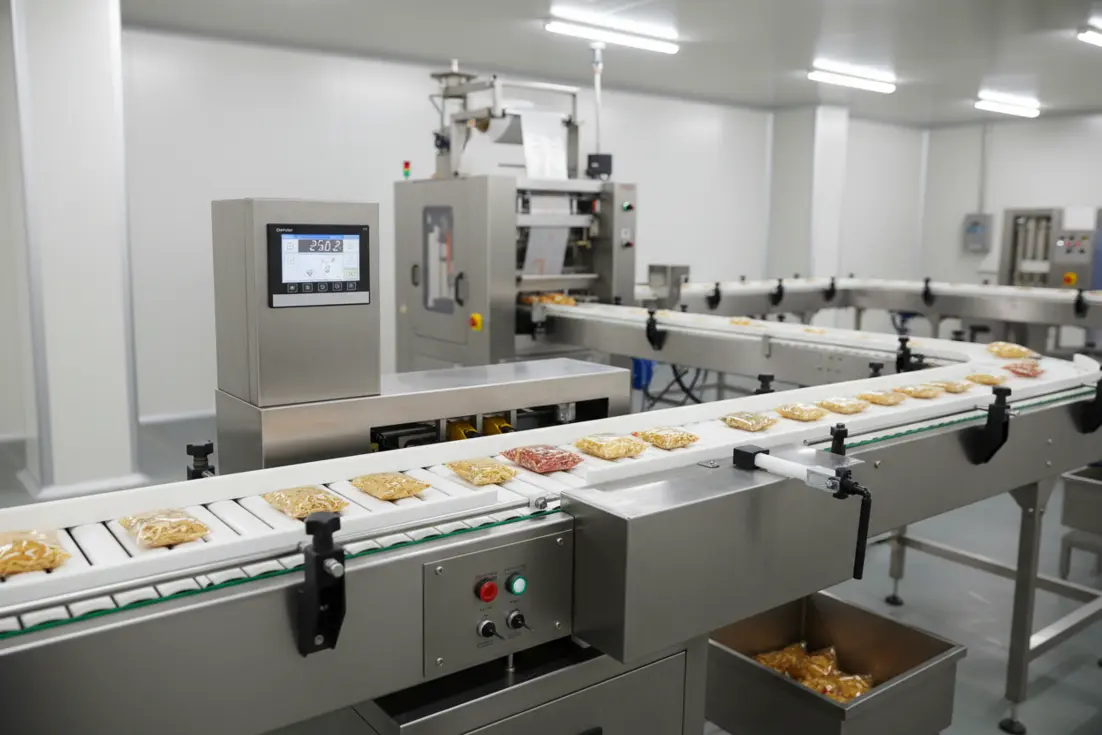
A machine fault that appears on an HMI is not automatically a PLC problem. On a food processing or packaging line, the PLC may only be reporting that a safety circuit is open, a sensor has not changed state, an air-pressure condition is missing, a drive is not ready, or a networked device has stopped communicating. The fastest route to recovery is to trace the failed condition through the whole signal path instead of changing program logic or replacing components by guesswork.
Effective PLC troubleshooting food manufacturing follows a fixed sequence: make the equipment safe, define the exact symptom, preserve evidence, identify the first failed condition, and then work from the field device through wiring and I/O to the PLC, logic, HMI, and output. This method is especially useful for intermittent faults, where a reset may restore production but erase the clues needed to prevent recurrence.
Start with a safe and defined machine state
Before opening a panel, checking terminals, or commanding an output, put the machine into a condition that matches the task. Follow the site’s energy-control procedure and the machine-specific instructions. A packaging machine can contain electrical, pneumatic, hydraulic, thermal, gravity, and stored mechanical energy. Clearing a jam or entering a guarded area can create hazards that are not visible from the HMI.
Do not bypass guards, safety devices, or interlocks to keep a line running. If a diagnostic test requires motion or energization, it should be planned and performed only by authorized personnel using the site’s approved procedure. The aim is to observe a condition safely, not to defeat the protection that detects it.
Next, describe the failure in operational terms. Avoid vague notes such as “PLC fault” or “machine stopped.” Record:
- The machine, station, and product or format running
- The exact alarm text, alarm number, and time shown
- What the machine was doing when it stopped
- Whether the stop occurs every cycle, after a changeover, only at speed, or only after running for some time
- What has already been reset, adjusted, replaced, or changed
- Relevant conditions such as washdown activity, cabinet heat, vibration, a recent sanitation period, utility interruption, or a new recipe
This converts a broad complaint into a testable symptom. “Carton erector faults occasionally” is difficult to isolate. “Magazine low sensor remains on after replenishment, but only during high-speed operation” gives a technician a usable starting point.
Preserve alarm and event evidence before resetting
An HMI alarm is often a symptom label rather than the root cause. Review the alarm history and event log before acknowledging or resetting the fault where possible. Look for the sequence of events immediately before the stop. A communication warning, drive-not-ready event, or low-air-pressure alarm may precede the final “machine stopped” message.
Capture useful evidence with approved tools and practices:
- Screenshots or photographs of alarm messages, timestamps, controller LEDs, and drive status indicators
- The active recipe, product format, and operating mode
- A short note of what operators observed: hesitation, missed product, unusual noise, delayed cylinder movement, or display freeze
- Any recurrence pattern by shift, product, speed, temperature, or operating area
A reset is a recovery action, not a diagnosis. If a reset clears a recurring fault, record that fact, then continue to investigate why the fault condition occurred.
Use drawings to map the complete signal path
A reliable PLC fault finding production line workflow begins with current documentation. Find the electrical schematic, I/O list, panel layout, pneumatic diagram where relevant, network drawing, and machine sequence or cause-and-effect description.
For the alarmed function, map the signal path in both directions:
- Field condition: What physical event should occur? For example, a container reaches a photoeye or a pneumatic cylinder reaches its extended position.
- Sensor or switch: What device detects that event, and what state should it produce?
- Wiring and terminals: Which cable, junction box, terminal, and input channel carry the signal?
- PLC input and logic: Which input address and program condition use the signal?
- Command and output: What output, drive command, valve, or actuator should respond?
- Feedback: What confirms the response actually happened?
- HMI display: Is the alarm based on the real field condition, a derived logic state, or a communication tag?
This prevents a common mistake: finding a false PLC input indication and immediately replacing the sensor. The issue may instead be a broken conductor, loose terminal, incorrect sensor alignment, insufficient supply voltage, damaged input channel, or a configuration mismatch.
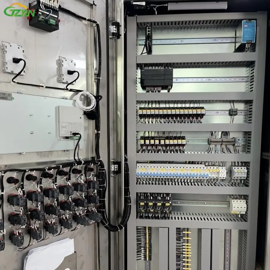
Source: image.made-in-china
Check the simplest physical causes first
Many food factory automation faults originate outside the PLC rack. Inspect the process and machine condition before making software changes.
Mechanical and product-related causes
A sensor may be functioning correctly while detecting a real mechanical problem. Check for product buildup, damaged guides, poor container presentation, misaligned rails, worn grippers, loose brackets, blocked photoeyes, incorrect format parts, and incomplete changeover settings. On high-speed packaging machinery, a small movement in a sensor bracket or actuator stop can cause inconsistent feedback.
Confirm that the expected motion is physically possible. A cylinder cannot make an “extended” sensor if it has lost air supply, is mechanically blocked, has a sticking valve, or is being prevented from moving by another sequence condition.
Sensor and field-device checks
Observe the device’s local status indicator if fitted, then compare it with the PLC input status. This is a powerful divide-and-check method:
| What you observe | Likely fault area to investigate |
|---|---|
| Sensor does not indicate when target is present | Sensor setup, alignment, contamination, target condition, local supply, or failed device |
| Sensor indicates correctly but PLC input does not change | Wiring, terminal connection, input module, input addressing, or electrical compatibility |
| PLC input changes but sequence does not advance | Logic permissives, mode selection, timer, recipe state, safety status, or upstream/downstream interlock |
| PLC output commands on but field device does not act | Output circuit, fuse, relay, valve coil, drive enable, actuator, utility supply, or mechanical obstruction |
| Field device operates but feedback never arrives | Feedback sensor, mechanical travel, wiring, input circuit, or sequence timeout setting |
Use properly rated test equipment and approved live-testing practices. Check voltage at meaningful points in the circuit, rather than relying only on an input LED. A module indicator may show a signal while the field device lacks a stable supply under load.
Verify control power, grounding, and cabinet conditions
If faults affect several unrelated devices, occur after motor starts, or appear during certain operating periods, widen the investigation beyond the individual alarm. Inspect the control power supply, fusing, terminals, grounding and bonding arrangements, cabinet temperature, moisture ingress, and cable condition.
Loose terminations, deteriorated connectors, vibration, and corrosion can create intermittent faults that disappear when a cabinet door is opened or wiring is disturbed. Check for signs of heat, discoloration, damaged insulation, water ingress, or loose terminal hardware according to the maintenance procedure.
Power quality and electrical noise may require a more detailed assessment when symptoms include controller resets, communication dropouts, multiple I/O anomalies, or faults associated with drives and motors operating. Cable routing and separation between power and low-level signal wiring can also matter, particularly after modifications. Do not assume that a PLC CPU is defective until supply and connection issues have been excluded.
Separate I/O, logic, network, and HMI problems
PLC software is most useful when it is used to observe the system, not as the first place to edit it. With authorization and the correct current program version, review controller status, module diagnostics, online I/O values, active faults, and the relevant logic path.
I/O faults
Compare the field-device indication, measured electrical condition, module LED, and online input or output state. If these do not agree, the mismatch identifies where to focus. Confirm the I/O address against the drawings; documentation that has not kept pace with machine changes can create misleading results.
Logic and sequence faults
If an input is correct but a commanded output is absent, look for the first unmet permissive. Common blockers include an unreset fault latch, manual mode, safety status, a recipe-dependent condition, a timer, a downstream machine not ready, or an incomplete homing sequence.
Do not force bits, defeat permissives, or alter timer values merely to prove that a mechanism can move unless the machine builder’s procedure and site controls specifically authorize the test. A forced output can create unexpected motion and can hide the actual sequence fault.
Network faults
For industrial Ethernet, fieldbus, remote I/O, drives, vision systems, printers, and other connected equipment, start with the device diagnostics and physical layer. Check module and switch indicators, connector seating, damaged cables, device power, and the fault history. Determine whether the problem is one node, one network segment, or a wider controller communication issue.
A network alarm can also be secondary. A powered-off remote I/O enclosure, tripped local supply, or moisture-damaged connector may present at the PLC as a communications loss.
HMI alarm faults
For industrial HMI alarm troubleshooting, verify whether the HMI is displaying a current PLC condition, a retained historical state, or a communication-quality problem. If the machine is physically ready but the screen remains alarmed, compare the HMI tag with the PLC value and confirm communications are healthy. If the PLC condition is correct but the HMI value is wrong, escalation may be needed for HMI configuration, tag mapping, or device communication diagnostics.
Handle intermittent faults as an evidence-collection task
Intermittent failures are often made worse by rapid part replacement. Instead, look for conditions that change when the fault occurs:
- Product type, package material, speed, or format
- Time since startup, washdown, cleanup, or changeover
- Cabinet temperature or nearby equipment heat
- Vibration, conveyor loading, or movement of a cable chain
- Motor, VFD, heater, or compressor operation
- Operator action or a specific sequence transition
Use a controlled observation plan. Where safe, run the machine under the conditions that normally produce the fault and monitor the relevant input, output, device diagnostic, and alarm sequence. A trend or data capture available in the control system may help establish which signal changed first.
Avoid changing several variables at once. If a sensor is adjusted, a connector is reseated, and a program change is made together, there is no dependable way to know which action resolved the issue.
Use controlled resets and protect the program
Before a reset, restart, download, or program change, determine what will be lost and who must approve the action. Preserve fault details and verify that the available program backup matches the installed controller and machine configuration.
A controller fault, corrupted configuration indication, repeated watchdog event, unexplained program mismatch, or safety-related control issue should be treated as an escalation point. Restore or modify software only through the facility’s authorized change-management process. Uncontrolled changes can introduce new faults, invalidate troubleshooting evidence, and make future support more difficult.
When to escalate to controls engineering or the supplier
Escalate when the fault cannot be isolated to a field condition, wiring issue, known component failure, or documented operating setting. Controls engineering or the equipment supplier should be involved when there is:
- A PLC CPU, safety controller, or remote I/O module fault that persists after basic supply and connection checks
- A suspected program, configuration, firmware, recipe, or HMI tag issue
- Repeated network instability without an obvious physical cause
- A fault that follows a machine modification, panel change, or incomplete commissioning activity
- A safety circuit fault or any condition that creates uncertain machine behavior
- A recurring fault with evidence collected but no confirmed root cause
Provide a concise escalation package: machine identification, program and hardware version where known, alarm history, photos or screenshots, measured observations, actions already taken, and the exact operating conditions that reproduce the problem. This is far more useful than reporting that the line “randomly faults.”
Close the job by documenting the cause and prevention
A repair is not complete when the machine restarts. Record the confirmed cause, corrective action, replacement part if any, test performed, and whether the original symptom was reproduced and cleared. Note temporary actions separately from permanent corrections.
For recurring problems, review whether preventive work should change. The answer may be a better sensor mounting arrangement, cable protection, terminal inspection, cabinet sealing, spare-part standardization, improved alarm text, updated drawings, or technician training. A structured troubleshooting record creates a reference for later shifts and helps distinguish a one-time failure from a developing reliability issue.
The practical principle is simple: start at the physical symptom, prove each stage of the signal path, and make only controlled changes. That approach reduces unnecessary PLC edits, avoids blind component replacement, and gives maintenance teams a repeatable way to restore food manufacturing equipment safely.
References
- PLC Troubleshooting: A Step-by-Step Guide for Maintenance Teams | ITC Learning. (n.d.). https://itclearning.com/blog/plc-troubleshooting
- PLC Troubleshooting Guide: Common Issues, Solutions & Maintenance Tips. (n.d.). https://mfgtechhub.com/plc-troubleshooting-guide
- PLC Troubleshooting: 8-Step Fault-Finding Guide (2026). (n.d.). https://plcprogramming.io/blog/plc-troubleshooting-complete-guide
- PLC Installation Troubleshooting and Maintenance Guide. (n.d.). https://r-aletqan.com/plc-installation-troubleshooting-and-maintenance
- Top 10 Most Common PLC Failures and How to Diagnose Them. (n.d.). https://epochtechnical.com/blog/top-10-most-common-plc-failures-and-how-to-diagnose-them
- Troubleshooting PLC Systems: A Systematic Approach to …. (n.d.). https://www.linkedin.com/pulse/troubleshooting-plc-systems-systematic-approach-finding-liam-bee-djwye
- OSHA Compliance for Food Manufacturing Maintenance Teams: Lockout/Tagout, Confined Spaces. (n.d.). https://oxmaint.com/industries/food-manufacturing/osha-compliance-food-manufacturing-maintenance-lockout-tagout
- Introduction to PLC Troubleshooting - itrustbot. (n.d.). https://itrustbot.com/blogs/blog/introduction-to-plc-troubleshooting